
Related Manuals for Sentiotec ARKTIS INFRA +


Summary of Contents for Sentiotec ARKTIS INFRA +
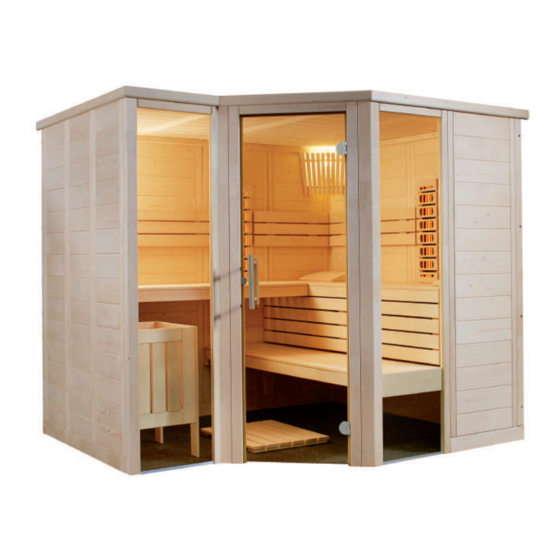
- Page 1 Solid wood sauna ARKTIS INFRA + 234 x 206 x 204 cm INSTRUCTIONS FOR INSTALLATION AND USE English ARKITS-IR+ Version 12/18 item no. 1-030-271...
-
Page 2: Table Of Contents
Table of Contents 1. Preparing for installation 1.1. Tools required 1.2. Maintenance and cleaning 1.3. Disposal 1.4. ARKTIS INFRA+ parts list 2. Cabin installation 2.1. Base frame installation 2.2. Wall element assembly 2.3. Ceiling installation 2.4. Ventilation slit installation 2.5. Installing interior fittings 2.6. -
Page 3: Preparing For Installation
These assembly instructions can also be found in the downloads section of our website: www.sentiotec.com/downloads. Important note: ● Before you begin work, check the parts list to ensure that all the individual parts have been delivered. -
Page 4: Tools Required
Instructions for installation and use p. 4/36 1.1. Tools required ● Hammer with a wooden head or a mallet ● Cordless screwdriver with bits for cross-head screws and Torx ● Roller tape measure ● Drill bits with a diameter of 3 mm, 10 mm, 20 - 30 mm (for sauna heater power cable) ●... -
Page 5: Maintenance And Cleaning
Instructions for installation and use p. 5/36 1.2. Maintenance and cleaning ● The sauna should be cleaned with a damp cloth. Only use warm water – no cleaning products. ● We recommend heating the cabin once a month if the sauna is not used for a long time. -
Page 6: Arktis Infra+ Parts List
Instructions for installation and use p. 6/36 1.4. ARKTIS INFRA+ parts list No. of Name Dimensions items Base frame 2 Base frame 204 x 9 x 4 cm 1 Base frame 138 x 9 x 4 cm 1 Base frame 61.5 x 9 x 4 cm 1 Base frame 32 x 9 x 4 cm... - Page 7 Instructions for installation and use p. 7/36 No. of Name Dimensions items Support slats 2 Roof support slat 115 x 4 x 4 cm 1 Roof support slat 196 x 4 x 4 cm 1 Roof support slat 136 x 4 x 4 cm 1 Roof support strip 1x 22.5 °...
- Page 8 Instructions for installation and use p. 8/36 No. of Name Dimensions items Glass elements 1 Glass door 191.5 x 68 x 0.8 cm 1 Glass element 194.5 x 48.1 x 0.8 cm 1 Glass element 194.5 x 46.4 x 0.8 cm Roof trim slats 1 Roof trim slat 1 x 45°...
-
Page 9: Cabin Installation
Instructions for installation and use p. 9/36 2. Cabin installation The cabin can have a right or left set-up; please note the corresponding floor plans on Page 33 and Page 34. 2.1. Base frame installation 204 cm + 32 cm Left floor plan 61.5 cm 3 mm drill bit, 4 screws 4 x 70 mm... -
Page 10: Wall Element Assembly
Instructions for installation and use p. 10/36 2.2. Wall element assembly The corner posts are connected to the wall elements using Multiclips. The other wall elements are connected tongue and groove and are screwed together. A always refers to the visible side. This is labelled on the top side of the wall elements. - Page 11 Instructions for installation and use p. 11/36 Installing corner posts with wall elements Pre-assemble the wall elements with the corner posts on the floor and then place these posts on the base frame. Insert the corner post from above down onto the wall elements. When doing this, ensure that the Multiclips are correctly aligned (see below).
- Page 12 Instructions for installation and use p. 12/36 Installing wall elements The electrical element has drill holes for laying cables. For the position see floor plans on Page 33 and Page 34. Width 55 cm Width 48 cm Width 55.6 cm Electrical element...
- Page 13 Instructions for installation and use p. 13/36 Screwing wall elements together Check the right angle before screwing the wall elements together. Observe the tip on page 4. 3 mm drill bit, 8 screws 4 x 70 mm...
- Page 14 Instructions for installation and use p. 14/36 Corner post and post for glass...
- Page 15 Instructions for installation and use p. 15/36 Glass elements 3 mm drill bit, 3 mm drill bit, 1 screw 4 x 70 mm 1 screw 4 x 70 mm...
- Page 16 Instructions for installation and use p. 16/36 Türstock einsetzen Remove transport strip from Insert door frame the door frame...
-
Page 17: Ceiling Installation
Instructions for installation and use p. 17/36 2.3. Ceiling installation Roof support slats 4 cm 21 screws 4 x 70 mm... - Page 18 Instructions for installation and use p. 18/36 Ceiling elements 3 mm drill bit, 15 screws 4 x 70 mm...
-
Page 19: Ventilation Slit Installation
Instructions for installation and use p. 19/36 2.4. Ventilation slit installation 3 mm drill bit, 4 screws 3.5 x 40 mm 2.5. Installing interior fittings Bench support slats 3 mm drill bit, 3 screws 5 x 70 mm 2 screws 4 x 60 mm... - Page 20 Instructions for installation and use p. 20/36 3 mm drill bit, 3 screws 5 x 70 mm 3 mm drill bit, 3 screws 5 x 70 mm...
- Page 21 Instructions for installation and use p. 21/36 Bench support slat with cover in front of glass element 2 screws 4 x 60 mm...
- Page 22 Instructions for installation and use p. 22/36 3 screws 5 x 70 mm 2 screws 4 x 60 mm...
- Page 23 Instructions for installation and use p. 23/36 Bench screen 4 screws 4 x 60 mm...
- Page 24 Instructions for installation and use p. 24/36 Bench 3 mm drill bit, 3 screws 5 x 70 mm...
- Page 25 Instructions for installation and use p. 25/36 Infrared radiator and backrests Connection box, top Label legible 4 screws 4 x 60 mm 4 screws 3 x 18 mm 3 mm drill bit, 8 screws 3.5 x 40 mm...
-
Page 26: Installing Accessories
Instructions for installation and use p. 26/36 2.6. Installing accessories Sauna lamp Insert lamp (not included in the scope of delivery) 3 mm drill bit, 2 screws 4 screws 3.5 x 40 mm... - Page 27 Instructions for installation and use p. 27/36 Heater protection grille Before installing the heater protection grille, drill the outlet for the heater cable in the electrical element. 4 screws 3.5 x 40 mm 4 screws 3.5 x 40 mm Symbol photo Symbol photo...
-
Page 28: Installing Glass Door
Instructions for installation and use p. 28/36 2.7. Installing glass door The glass door can be hinged to the left or right. Insert a silicone or paper insert for glass door fittings on both sides of the glass door. Screws 4 x 30 mm... - Page 29 Instructions for installation and use p. 29/36 Door handle and sleeve plate Attach plastic washers on Insert silicone ring in the drill holes the stainless steel handle...
- Page 30 Instructions for installation and use p. 30/36 Door magnet...
-
Page 31: Installing Roof Trim
Instructions for installation and use p. 31/36 2.8. Installing roof trim Install the roof trim only after you have inserted the cable to the sauna heater and to the sauna control unit. The slat on the electrical element may possibly have to be cropped. 3 mm drill bit, 11 screws 3.5 x 40 mm... -
Page 32: Installing Ceiling Cover Slat
Instructions for installation and use p. 32/36 2.9. Installing ceiling cover slat Install the ceiling cover slat only after you have inserted the cable to the sauna heater and to the sauna control unit. The slat on the electrical element may possibly have to be cropped. 20 screws 3.5 x 40 mm... -
Page 33: Floor Plan
Instructions for installation and use p. 33/36 3. Floor plan 3.1. Left floor plan... -
Page 34: Right Floor Plan
Instructions for installation and use p. 34/36 3.2. Right floor plan... -
Page 35: Changes For The Right Floor Plan Installation
Instructions for installation and use p. 35/36 3.3. Changes for the right floor plan installation For installing corner posts and posts for the glass (page 14) Remove the Multiclips from the corner posts and the post for the glass. Use the supplied template for the new positioning of the Multiclips. Multiclips... - Page 36 Instructions for installation and use p. 36/36...
Need help?
Do you have a question about the ARKTIS INFRA + and is the answer not in the manual?
Questions and answers