Crestron DM-NVX-351 Product Manual
Dm nvx 4k60 4:4:4 hdr
network av encoders/decoders
Hide thumbs
Also See for DM-NVX-351:
- Product manual (96 pages) ,
- Design manual (42 pages) ,
- Quick start manual (9 pages)

Related Manuals for Crestron DM-NVX-351


Summary of Contents for Crestron DM-NVX-351
- Page 1 DM NVX™ 4K60 4:4:4 HDR Network AV Encoders/Decoders Product Manual Crestron Electronics, Inc.
- Page 2 States and/or other countries. Other trademarks, registered trademarks, and trade names may be used in this document to refer to either the entities claiming the marks and names or their products. Crestron disclaims any proprietary interest in the marks and names of others. Crestron is not responsible for errors in typography or photography.
-
Page 3: Table Of Contents
Contents Introduction ........................... 1 Physical Description ........................2 DM-NVX-350 and DM-NVX-351 ................................ 2 Front Panel ......................................... 2 Rear Panel ........................................3 DM-NVX-350C and DM-NVX-351C ..............................5 Configuration and Status ......................7 DMF-CI-8 Chassis Details ..................................8 Using the Web Interface................................8 Using SIMPL Windows .................................. - Page 4 USB 2.0 Routing ......................................28 Using the Web Interface................................28 Using SIMPL Windows ................................... 29 Device Mode Locking ....................................30 Crestron XiO Cloud Service Connection ........................... 31 Automatic Firmware Update................................32 HDCP 2.2 Compliance....................... 33 IGMP Snooping .......................... 34 Troubleshooting ......................... 36 Appendix: Device Discovery .....................
-
Page 5: Introduction
• Troubleshooting guidelines • In addition, information about device discovery of a DM NVX device using Crestron Toolbox™ software is provided in the appendix of this manual. For installation information, refer to the DM-NVX-350/DM-NVX-351 DO Guide (Doc. 7799) and the DM-NVX-350C/DM-NVX-351C DO Guide (Doc. -
Page 6: Physical Description
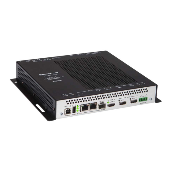
DM NVX devices. DM-NVX-350 and DM-NVX-351 This section provides information about the connectors, controls, and indicators that are available on the front and rear panels of the DM-NVX-350 and DM-NVX-351 stand-alone endpoints. Front Panel The following illustration shows the front panel of the DM-NVX-350 and DM-NVX-351. -
Page 7: Rear Panel
Green RX LED indicates that unit is in receiver (decoder) mode; Green OL LED indicates an online connection to a control system via Ethernet Device control via RS-232, IR, CEC, or Ethernet requires integration with a Crestron control system. The DEVICE and HOST ports cannot be used simultaneously. - Page 8 LAN connection, the port requires connection to a 1000BASE-T switch in order to stream network video. The DM-NVX-350 and DM-NVX-351 can be powered by the connection of LAN 1 to a Crestron DM-PSU-ULTRA-MIDSPAN or other Crestron approved power injector (sold separately). For additional information, refer to Answer ID 5791 in the Online Help section of the Crestron website (www.crestron.com/onlinehelp).
-
Page 9: Dm-Nvx-350C And Dm-Nvx-351C
LAN 3 can be used as the primary LAN connection or can be connected to another DM NVX device. LAN 3 can connect to a fiber-optic network using the appropriate Crestron SFP-1G transceiver module (sold separately). Refer to the SFP-1G Series Installation Guide (Doc. 7979) for information about installing Crestron SFP-1G Series transceiver modules. - Page 10 HDMI OUTPUT: 19-pin Type A HDMI female; HDMI digital video/audio output (DVI compatible)* HDMI INPUTS 1–2: 19-pin Type A HDMI female; HDMI digital video/audio inputs (DVI and Dual-Mode DisplayPort compatible)* AUDIO I/O: 5-pin 3.5 mm detachable terminal block; ...
-
Page 11: Configuration And Status
Analog audio input or output • Breakaway audio • USB 2.0 routing • Device mode locking • Crestron XiO Cloud™ service connection • Automatic firmware update • Product Manual – DOC. 7839G DM NVX 4K60 4:4:4 HDR Network AV Encoders/Decoders • 7... -
Page 12: Dmf-Ci-8 Chassis Details
DMF-CI-8 Chassis Details NOTE: DMF-CI-8 chassis details apply only to the DM NVX cards and do not apply to the DM NVX stand-alone endpoints. DMF-CI-8 chassis information can be viewed using the web interface or SIMPL Windows. Using the Web Interface For a DM NVX card, view DMF-CI-8 chassis information on the Status page. -
Page 13: Dm Xio Director Network Appliance Details
DM XiO Director Network Appliance Details If a DM NVX device is managed by a DM XiO Director network appliance, DM XiO Director network appliance details can be viewed using the web interface. View DM XiO Director network appliance details on the Status page. The DM XiO Director section of the page displays the following information: DM XiO Director network appliance host name •... -
Page 14: Using The Web Interface
Using the Web Interface Set the operating mode of the DM NVX device on the Stream page. In the Mode drop-down list, select Receiver or Transmitter. The default setting is Receiver (decoder). Stream Page - Mode Configuration When a different mode is selected, a prompt appears asking for confirmation that the device be rebooted. -
Page 15: Stream Statistics
Stream Statistics Statistics can be displayed to indicate the number of packets received or transmitted, the number of dropped packets, and the bit rate of the received or transmitted stream. To enable or disable stream statistics, use the web interface or SIMPL Windows as discussed in the following sections. -
Page 16: Using The Web Interface
Using the Web Interface Configure multicast TTL on the Stream page. In the Advanced section of the page, set a multicast TTL value: Set Auto Initiation to Disabled. 2. Stop the stream by clicking Stop. 3. Select the Custom TTL checkbox. 4. -
Page 17: Dscp
DSCP NOTE: DSCP (Differentiated Services Code Point) applies only to a DM NVX device that is operating as a transmitter. To implement Quality of Service (QoS), IP networks use the DSCP value. Within an IP packet header, the DSCP defines a value from 0 to 63 that maps to a certain traffic classification. -
Page 18: Automatic Routing Of Video Inputs
Automatic Routing of Video Inputs Automatic routing between video inputs can be enabled or disabled. When automatic routing is enabled, the device automatically routes the last connected input. To configure automatic routing, use the web interface or SIMPL Windows as discussed in the following sections. -
Page 19: Using The Web Interface
Using the Web Interface Configure video wall processing on the Output page. In the Layout section of the page: Select the Video Wall radio button. 2. In the Width combo box, select the desired number of rows of displays. 3. In the Height combo box, select the desired number of columns of displays. 4. -
Page 20: Using Simpl Windows
Using SIMPL Windows Configure a video wall in Slot-06: HDMI OUT: Set the <VideoWallMode>, <Horizontal_Bezel_Compensation>, and <Vertical_Bezel_Compensation> analog input joins to the desired values. 2. Repeat step 1 for each DM NVX receiver that connects to a display for inclusion in the video wall. -
Page 21: Using Simpl Windows
Using SIMPL Windows Adjust underscan in Slot-06: HDMI Out. Set the <Underscan> analog input join to the desired value. For additional information, refer to the SIMPL Windows help file. User-Selectable Output Resolution NOTE: User-selectable output resolution applies only to a DM NVX device that functions as a receiver. -
Page 22: Maximum Color Depth And Color Space Mode
Maximum Color Depth and Color Space Mode Configure the maximum color depth (maximum bit depth supported by the output) and HDMI color space mode using the web interface or SIMPL Windows. Using the Web Interface Configure maximum color depth and color space mode on the Output page. In the HDMI Output Setting section of the page: Configure maximum color depth in the Max Color Depth drop-down list by •... -
Page 23: Using Simpl Windows
Using SIMPL Windows Configure maximum color depth and color space mode in Slot-06: HDMI Out. Set the <MaximumColorDepth> analog input join to the appropriate value for the maximum bit depth supported by the output. Set the <ColorSpaceMode> analog input join to the desired value for the HDMI color space. -
Page 24: Subscriptions
Main Inputs Page - EDID Configuration Input-Specific Page - EDID Configuration (HDMI Input 1 Page Shown) Subscriptions NOTE: Subscriptions apply only to a DM NVX device that functions as a receiver. Subscription of a DM NVX transmitter to a DM NVX receiver sets up Real Time Streaming Protocol (RTSP) negotiation between the DM NVX receiver and the DM NVX transmitter. -
Page 25: Using The Web Interface
Using the Web Interface Configure subscriptions on the Subscriptions and Routing pages: On the Subscriptions page, do either of the following: a. In the Subscribed Streams section, manually add each transmitter that is to be subscribed to the receiver or load one or more existing subscription lists (*.xiolist). -
Page 26: Using Simpl Windows
2. In the Xio-Routing section of the Routing page, select the desired transmitter to be routed to the receiver. Routing Page For additional information, refer to the online help of the web interface. Using SIMPL Windows NOTE: Selection of the transmitters for subscription or selection of subscription lists can be performed using the web interface only. -
Page 27: Daisy Chain
Daisy Chain A DM NVX device includes three LAN ports (two RJ-45 LAN ports and one SFP LAN port) that can be used to daisy chain multiple DM NVX devices. In a daisy chain configuration, the DM NVX devices connect directly to one another in a series. The daisy chain configuration can consist of one transmitter and up to 64 receivers or can include receivers only (maximum of 64). -
Page 28: Switching Nonsubscribed Transmitters
Switching Nonsubscribed Transmitters To switch nonsubscribed transmitters in a daisy chain configuration, use the web interface or SIMPL Windows. Using the Web Interface To switch nonsubscribed transmitters, do the following on the Stream page: For each receiver in the daisy chain, disable Auto Initiation and then stop the stream. -
Page 29: 7.1 Surround Sound Audio
HDMI inputs. NOTE: Analog audio output from a DM-NVX-350 or DM-NVX-350C is functional only when the device is receiving a 2-channel stereo input signal. The DM-NVX-351 and DM-NVX-351C can derive a 2-channel downmix signal from a multichannel surround sound source. -
Page 30: Using The Web Interface
Using the Web Interface Configure analog audio on the Routing and Output pages as applicable: On the Routing page, set Analog Audio Mode to Insert or Extract. Routing Page - Analog Audio Mode Configuration 2. (Applicable only when Audio Mode is set to Insert) On the Routing page, set Audio Source to Analog Audio. -
Page 31: Using Simpl Windows
Using SIMPL Windows NOTE: To insert or extract analog audio, use the web interface. Using the top-level programming slot for the DM NVX device, set the <AudioSource> analog input join to Analog Audio if analog audio is to be inserted into a network video stream or the HDMI output. -
Page 32: Usb 2.0 Routing
NOTE: DM NVX devices are engineered to deliver maximum compatibility with the widest possible range of USB products. Crestron does not guarantee that all USB products are compatible with DM NVX devices. NOTE: When using high-traffic USB devices, bandwidth management must be considered. -
Page 33: Using Simpl Windows
To remove pairing between two DM NVX devices, click the UnPair button for each device in the pair. USB Routing Page For additional information, refer to the online help of the web interface. Using SIMPL Windows Using SIMPL Windows, configure USB routing in Slot 30: USB: Determine the two DM NVX devices that are to be paired: One DM NVX device functions as the local extender (LEX);... -
Page 34: Device Mode Locking
Device Mode Locking Device mode locking controls whether the SETUP button on a DM NVX stand-alone endpoint and the front panel of a DMF-CI-8 card chassis can be used to set the operating mode of a DM NVX device as a transmitter or receiver. NOTE: Device mode locking does not apply to the Mode setting on the Stream page of the web interface. -
Page 35: Crestron Xio Cloud Service Connection
Connection to the Crestron XiO Cloud service can be enabled or disabled using the web interface. Configure the connection to the Crestron XiO Cloud service on the Device page. In the Cloud Settings section of the page, set Cloud Configuration Service Connection to Enabled (default setting) or Disabled. -
Page 36: Automatic Firmware Update
A DM NXV device can be automatically updated with the latest firmware at scheduled intervals. To configure automatic firmware update: Using the Crestron Auto Update Tool, generate a manifest file (*. mft). The file is placed on an FTP (File Transfer Protocol) or SFTP (Secure File Transfer Protocol) server. -
Page 37: Hdcp 2.2 Compliance
Device Page – Auto Update HDCP 2.2 Compliance DM NVX devices are compliant with HDCP 2.2. HDCP 2.2, commonly referred to as HDCP 2, is the next generation of HDCP (High-Definition Content Protection). Note the following about HDCP 2: Compared to HDCP 1, HDCP 2 brings a higher level of cryptographic protection •... -
Page 38: Igmp Snooping
IGMP Snooping A DM NVX device sends IGMP join and leave messages. NOTE: DM NVX devices support IGMPv2 and IGMPv3 only. IGMPv1 is not supported. The IGMP snooping support version (v2 or v3) is configurable in the web interface. The Network Interface section of the Network page allows the desired version to be selected. - Page 39 Because only the least significant 23 bits of the IP address are mapped to Ethernet addresses (RFC 1112), there is a loss of information when forwarding solely on the destination MAC address. For example, IP addresses 224.0.0.123 and 239.128.0.123 and similar IP multicast addresses all map to MAC address 01-00-5e-00-00-7b for Ethernet.
-
Page 40: Troubleshooting
Troubleshooting The following table provides troubleshooting information. If further assistance is required, contact a Crestron customer service representative. DM NVX Encoder/Decoder Troubleshooting PROBLEM POSSIBLE CAUSE(S) CORRECTIVE ACTION 4K60 4:4:4 2-channel non-HDR or The display device is not Configure the display device properly. - Page 41 DM NVX Encoder/Decoder Troubleshooting (Continued) PROBLEM POSSIBLE CAUSE(S) CORRECTIVE ACTION The analog audio input is not The analog audio mode is set to Set the analog audio mode to insert functioning. extract audio. audio. An incorrect audio source is Set the audio source to analog audio. selected.
- Page 42 On the Device page of the web interface, click the Restore button. • From the Tools menu in the Crestron Toolbox software, select Text Console and • issue the restore command. Power cycle the device 10 times. After the tenth power cycle, wait until the device •...
-
Page 43: Appendix: Device Discovery
NOTE: The security software running on the computer may send a program alert regarding the attempt of the Crestron Toolbox software to connect to the network. Allow the connection so that the Device Discovery Tool can be used. The DM NVX device is discovered and is listed in the device list on the left side of the screen. - Page 44 Device Administration Login Page 6. Enter the user name and password. The default user name and password are admin both NOTE: The user name and password are case sensitive. 7. Click Sign In. The Status page of the DM NVX device opens. For additional information, refer to the online help of the web interface.
- Page 45 This page is intentionally left blank. Product Manual – DOC. 7839G DM NVX 4K60 4:4:4 HDR Network AV Encoders/Decoders • 41...
- Page 46 Crestron Electronics, Inc. Product Manual – DOC. 7839G 15 Volvo Drive Rockleigh, NJ 07647 (2045243) Tel: 888.CRESTRON 09.18 Fax: 201.767.7576 Specifications subject to www.crestron.com change without notice.
Need help?
Do you have a question about the DM-NVX-351 and is the answer not in the manual?
Questions and answers