Crestron DM-NVX-352C Quick Start
Network av encoder/decoder card
Hide thumbs
Also See for DM-NVX-352C:
- Product manual (96 pages) ,
- Interface manual (85 pages) ,
- Design manual (42 pages)
Advertisement
Quick Links
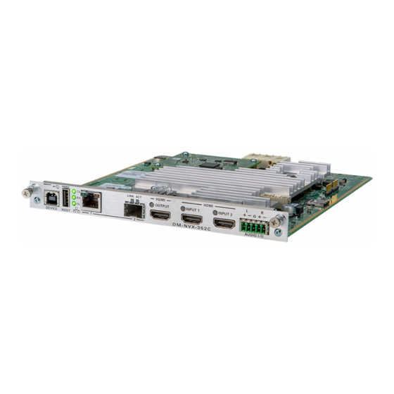
DM-NVX-352C
DM NVX™ Network AV Encoder/Decoder Card
The Crestron® DM-NVX-352C network AV encoder/decoder card transports ultra high-definition
4K60 4:4:4 HDR video over standard Gigabit Ethernet. Engineered to function as either an
encoder or decoder, the DM-NVX-352C features secure web-based control and management,
two auto-switching HDMI® inputs and one HDMI output, an analog audio input or output, USB
and KVM integration, video wall processing, and support for copper and fiber LAN connectivity.
The DM-NVX-352C also supports Dante® audio networking and AES67.
Check the Box
Item
DM-NVX-352C
Cable, USB 2.0, A - B, 6' (1.83 m) (P/N 2014966)
Connector, 5-Pin (P/N 2003577)
Install the Card
The DM-NVX-352C is designed to occupy the DMF-CI-8 chassis.
CAUTIONS:
•
DM NVX™ cards are susceptible to damage from electrostatic discharge (ESD).
Observe standard ESD precautions when handling the cards. Wear an ESD wrist strap
that is connected to ground, and place the cards on grounded surfaces only.
•
To prevent damage to a card that is connected to cables, disconnect all cables from the
card before installing the card into a card slot or removing the card.
NOTES:
•
In a new installation of the DMF-CI-8, it is recommended that the cards be installed before
power is applied to the chassis. In an existing installation of the DMF-CI-8, the cards can
be added or replaced without the need to shut down the chassis—the cards are
hot swappable.
•
When installing the cards into a partially populated DMF-CI-8, install the cards into slots
5–8 before using slots 1–4. Doing so ensures better cooling and lower power consumption.
In addition, always cover empty slots using the filler plates included with the chassis.
To install a card into the DMF-CI-8:
1.
Using a #2 Phillips screwdriver (not included) or your fingers, remove the filler plate of an
unused slot by loosening the two captive panel screws.
Filler
plate
(2) Captive
panel screws
2.
Carefully insert the card into the card guides of the selected slot, and then push the card
inward until it engages the chassis backplane.
Qty
1
1
1
DM NVX™ card
3.
Finger-tighten the two captive panel screws to secure the card—do not overtighten
the screws.
Connect the Card
Connect the card as required for the application.
NOTES:
•
The DM-NVX-352C can be configured to use either the DEVICE port or the HOST port.
Both ports cannot be used simultaneously.
•
The DM-NVX-352C provides two LAN ( ) ports. LAN port 1 is a 10BASE-T/100BASE-TX/
1000BASE-T port. LAN port 2 is an SFP port that connects to a fiber-optic network using
the appropriate SFP-1G transceiver module. (Refer to the SFP-1G Series Installation Guide
[Doc. 7979] for information about installing Crestron SFP-1G Series transceiver modules.)
Only one LAN port at a time can be used as the primary LAN connection to stream
network video, allowing the other port to be used for connection to a local network device
or to another DM NVX device. When a LAN port is used as the primary LAN connection,
the port must connect to a 1000BASE-T switch in order to stream network video.
TX, RX,
and OL
LEDs
DMF-CI-8
DEVICE:
HOST:
To
To
USB
USB
host
device
DMF-CI-8
Green
Amber
HDMI®
OUTPUT LED
LED
LED
LINK
ACT
HDMI
HDMI
LED
LED
INPUT 1 LED
INPUT 2 LED
1:
2:
HDMI
HDMI
To SFP
OUTPUT:
INPUTS
1–2:
10BASE-T/
100BASE-TX/
port of
To
From
Ethernet
HDMI
audio/video
1000BASE-T to
switch or
display
sources
Ethernet switch,
local network
other
DM NVX
device, or
other DM NVX
device
device
AUDIO I/O Connector Pin Assignments
The AUDIO I/O connector uses a 5-pin terminal block for balanced or unbalanced analog audio
input or output.
AUDIO I/O Connector
+
–
+ –
Balanced/Unbalanced Audio Input
Refer to the following table and diagrams for analog audio input pin assignments and
connection information.
Signal Name
Balanced Audio Input
Unbalanced Audio Input
+
L+
L+ In
–
L–
L– signal return, jumper to GND
G
Shield/ground
Ground
+
R+
R+ In
–
R–
R– signal return, jumper to GND
Balanced Input
Unbalanced Input
L
R
L
+ - G + -
+ - G + -
Shield
+
+
Source L
Source L
Shield
+
+
Source R
Source R
Shield
Balanced/Unbalanced Audio Output
Refer to the following table and diagrams for analog audio output pin assignments and
connection information.
Signal Name
Balanced Audio Output
+
L+
–
L–
G
Shield/ground
+
R+
–
R–
Balanced Output
Unbalanced Output
L
R
L
R
+ - G + -
+ - G + -
AUDIO I/O:
Shield
Balanced/
+
unbalanced
Right
+
stereo line
AMP
level audio
input or
Left
+
+
output
Quick Start
R
Jumpers
Unbalanced Audio Output
L+ Out
Open
Common ground
R+ Out
Open
Right
AMP
Left
Advertisement

Related Manuals for Crestron DM-NVX-352C


Summary of Contents for Crestron DM-NVX-352C
- Page 1 • In a new installation of the DMF-CI-8, it is recommended that the cards be installed before • The DM-NVX-352C can be configured to use either the DEVICE port or the HOST port. Source L Source L power is applied to the chassis. In an existing installation of the DMF-CI-8, the cards can Shield Both ports cannot be used simultaneously.
- Page 2 The product is a class 1 laser product. It complies with safety regulations of IEC 60825-1, FDA 21 CFR 1040.11 and FDA 21 CFR may be used in this document to refer to either the entities claiming the marks and names or their products. Crestron disclaims user’s authority to operate the equipment.
Need help?
Do you have a question about the DM-NVX-352C and is the answer not in the manual?
Questions and answers