
Related Manuals for Kospel EKCO.L1 z


Summary of Contents for Kospel EKCO.L1 z
- Page 1 SERVICE MANUAL EKCO.L1 z EKCO.L1N z EKCO.L1 p EKCO.L1N p EKCO36.L1 EKCO36.L1N 16.06.2010 KOSPEL S.A. KOSZALIN ul. Olchowa 1...
-
Page 2: Table Of Contents
Pic.3 ZIO-21 (interconnect) connecting board 4. Failures Table of faults for EKCO.L1 (PSK.P4) 5. Boiler construction Pic.4a Boiler EKCO.L1 z, EKCO.L1 p, EKCO36.L1 Pic.4b Boiler EKCO.L1N z, EKCO.L1N p, EKCO36.L1N 9 6. Heating box Pic.5 Heating box 7. Power board Pic.6... -
Page 3: Front View
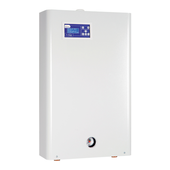
Front view Pic.1a EKCO.L1 z, EKCO.L1 p, EKCO36.L1 Pic.1b EKCO.L1N z, EKCO.L1N p, EKCO36.L1N... - Page 4 Control panel settings PSK.P4 front panel service mode configuration. To set the service modes turn off the boiler by pressing and holding the power button. Then press and hold the right arrow button and simultaneously press the power button. Use the upper and lower arrow buttons to change the parameter value or mode.
-
Page 5: Front Panel Handling
Pic.2 Front panel PSK.P4 - heat exchanger indicator - pump and flow indicator - heating on and room thermostat indicator - inlet temperature indicator - outlet temperature indicator - medium temperature setting indicator G, H, I - measurement value indicators - LCD display - temperature of water in the heat exchanger indicator symmetry error indication... -
Page 6: Pic.3 Zio-21 (Interconnect) Connecting Board
ZIO-21 board Pic.3 ZIO-21 board JUMPER JUMPER black brown blue PUMP Tzas – DHWT water electronic temperature sensor DS-1820 WZ – DHWT thermostat – jumper or room thermostat jumper or superior device ZAS – three way valve ZM – power module (ribbon cable) PSK.P4 cable (ribbon cable 5 pin) X.NA - PSK.P4 cable (ribbon cable 2 pin) -
Page 7: Failures
Failures Table 2. EKCO.L1/EKCO36.L1 (PSK.P4) Symptoms Reason Operation Check the mains and the main fuses. Check the WT-3 temperature cut-off. Front panel indicators are off. Power supply failure. Check the F2 fuse on ZIO-21 board. Replace the control panel. Check mains and the main fuses. Asymetric mains supply (only three phase boilers). -
Page 8: Boiler Construction
Boiler construction Pic.4a Boiler EKCO.L1, EKCO.L1p, EKCO36.L1 11 - 01010 24 - 00516 / 00489 14 - 00936 26 - 00001 41 - 00272 19 - 00790 20 - 00791 Tout 1 - Table 10 - 00786 page 10 17 - Table page 10 22 - Table page 18... -
Page 9: Pic.4B Boiler Ekco.l1Nz, Ekco.l1Np, Ekco36.L1N
Pic.4b Boiler EKCO.L1Nz, EKCO.L1Np, EKCO36.L1N Note: Only parts that differs from EKCO.L1 are shown separately 9 - 01251 10 - 01252 22 - Table page 18 42 - 00373 12 - 00784 21 - Table page 18 28 - 00853 42 - 00373 41 - 00272 41 - 00272... -
Page 10: Heating Box
Heating box Table 3 Pic.5 Heating box Amo- unt of heating Service Heating element Side view Boiler type Heating element Heating supply current code box type ating supply resistance ele- voltage ments [Ω] Automatic air vent EKCO.L1F-4 01022 ver.12 74,20 ÷ 82,00 2,80 ÷... -
Page 11: Dhwt Connection Chart
DHWT electric connection chart The VCZMH600E is an example of the three-way valve for the DHWT and central heating systems separated. The valve should come together with the VC6012ZZ00 servo and the 45900445-013B wire. Switching of the valve requires 230V mains connnection to be applied to brown or black wire. The blue wire should be connected to the mains neutral connector. -
Page 12: Cascade Unit For A Heating System With Two Or More Heating Boilers
Cascade unit for a heating system with two or more heating boilers . Cascade system enables possibility to increase maximum power output by parallel connection of several boilers. Cascade system uses the EKCO.M1 as master boiler and up to 8 Slim boilers as slaves. This system is controlled by one main control panel with the weather controlling system. -
Page 13: Pic.10 Psk.m2 (Master) And Psk.p4 (Slave) Connecting Diagram
Install all boilers and connect mains as pictured in manual. The slave boilers should be connected to the master by two wires connected to the control panel as in pic. 10. Use the twin wire LIYY 2x0.14. Use this wire to make a series of connections of A and B connectors in all boilers. -
Page 14: Wiring System
10. Wiring diagram Pic.11 Ver. I EKCO.L1, EKCO.L1N 12kW, 15kW, 18kW, 21kW, 24kW, 30kW, 36kW. Service Manual... -
Page 15: Pic.12 Ver.ii Ekco.l1 4Kw, 8Kw, 6Kw / 400V
Pic.12 Ver.II EKCO.L1, EKCO.L1N 4kW, 6kW, 8kW. -
Page 16: Pic.13 Ver.iii Ekco.l1 4Kw, 8Kw, 6Kw / 230V
Pic.13 Ver.III EKCO.L1F, EKCO.L1NF 4kW, 6kW, 8kW. Service Manual... -
Page 17: 11. Simplified Schema Of Internal Connections
11. Simplified schema of internal connections. Pic.14 Simplified schema of internal connections External Room DHWT switch off thermostat Thermostat Three way valve 1820 servo jumper Tzas W Z R P N A jumper ZIO 21 LB black LA brown N blue Heating PUMP PSK P4... - Page 18 12. Parts list. Table 4 Amount (pcs.) pos. service code picture no description notice 01022 EKCO.L-01.00.00a/5 Heating box 12 / 400V 01023 EKCO.L-01.00.00a/4 Heating box 15 / 400V 01024 EKCO.L-01.00.00a/3 Heating box 18 / 400V 01025 EKCO.L-01.00.00a/2 Heating box 21 / 400V 01026 EKCO.L-01.00.00a/1 Heating box 24 / 400V...
-
Page 19: Boiler Component Parts List
00035 Manometer M53-0..0,4 Mpa 00001 Automatic air-vent G1/2” 00225 Pump (UPS 15-50 130 lub RS 15/5-3) 00506 Pump (UPSO 15-70 130 9H) 00853 Expansion vessel (CP387 G1/2” 6L) 00492 EPCO.M-04.00.00 Pump connection pipe 00253 Gasket 1,5x14,8x8 00272 Gasket 1,5x18,2x11,7 00373 Gasket 1,5x20x13 00647 Gasket 2x30x21... -
Page 20: 13. Technical Data
Mini. connecting wires section 5 x 1 5 x 1,5 5 x 2,5 5 x 4 5 x 6 Max. connecting wires section 5 x 16 *Relates to EKCO.p for underfloor heating Copiled by Paweł Wojtanowski Copyright Kospel S.A. Service Manual...
Need help?
Do you have a question about the EKCO.L1 z and is the answer not in the manual?
Questions and answers