
Related Manuals for Kospel EKCO.L2N


Summary of Contents for Kospel EKCO.L2N
- Page 1 SERVICE MANUAL EKCO.L2N EKCO.L2Np EKCO.L2NF 14.03.2016 KOSPEL S.A. KOSZALIN ul. Ol cho wa 1...
-
Page 2: Table Of Contents
Externel view. 1.1 External view - open case. Pic.2. Boiler with open case (flow sensor Kospel - date of production before 29-03-2011). Pic.3. Boiler with open case (flow sensor HubaControl - date of production after 29-03-2011). 2. Construction of boilers. -
Page 3: External View Of Boilers
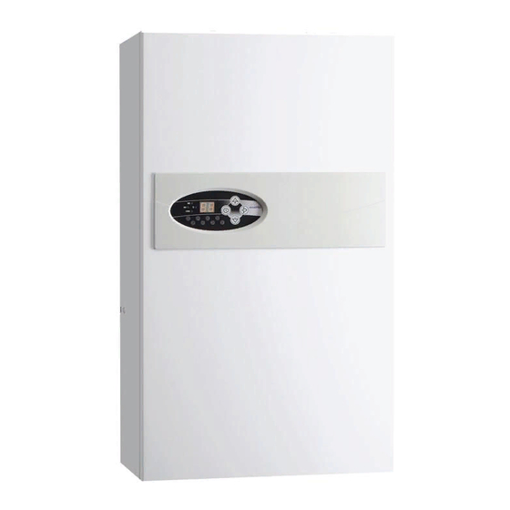
1. Exterior view of boilers. Pic.1. Exterior view. 01181 01179 01182 Part number in table of parts 01180 01168 Service code... -
Page 4: External View - Open Case
1.1. Exterior view - open case. Pic.2. Boiler with open case (flow sensor Kospel) - date of production before 29-03-2011. 01179 01180 Service manual EKCO.L2N... -
Page 5: Pic.3. Boiler With Open Case (Flow Sensor Hubacontrol - Date Of Production After 29-03-2011)
Pic.3. Boiler with open case (flow sensor Huba Control) - date of production after 29-03-2011. 01179 01180... -
Page 6: Construction Of Boilers
2. Construction of boilers. Pic.4. Construction of boilers (flow sensor Kospel) - date of production before 29-03-2011. 17 - 01182 27 - 00516 (100 C) 25 - 00001 27 - 00489 ( 75 C) 35 - 00253 21 - 00791... -
Page 7: Pic.5. Construction Of Boilers(Flow Sensor Hubacontrol - Date Of Production After 29-03-2011)
Pic.5. Construction of boilers (flow sensor Huba Control) - date of production after 29-03-2011. 17 - 01182 27 - 00516 (100°C) 25 - 00001 00489 (75°C) 27 - 35 - 00253 22 - 01541 after 11-08-2014 Tout 21 - 00791 1 - Table page 18 Tout 37 - 00882... -
Page 8: Construction Of Boilers - Water Part
2.1. Construction of boilers - hydraulic part. Pic.6. Hydraulic connection (flow sensor Kospel) - date of production before 29-03-2011. Service manual EKCO.L2N... -
Page 9: Pic.7. Hydraulic Connection (Flow Sensor Huba Control) - Date Of Production After 29-03-2011
Pic.7. Hydraulic connection (flow sensor Huba Control) - date of production after 29-03-2011. -
Page 10: Construction Of Boilers - View Of Expansion Vessel
2.2. Construction of boilers - view of expansion vessel. Pic.8. View of expansion vessel (flow sensor Kospel) - date of production before 29-03-2011. 14 - 00853 13 - 01187 37 - 00882 36 - 00255 37 - 00882 Service manual EKCO.L2N... -
Page 11: Pic.9. View Of Expansion Vessel (Flow Sensor Huba Control) - Date Of Production After 29-03-2011
Pic.9. View of expansion vessel (flow sensor Huba Control) - date of production after 29-03-2011. 14 - 00853 37 - 00882... -
Page 12: Assembly Of Flow Sensor
Incorrect installation of the flow sensor, and the incorrect setting in the service menu can result to incorrect measurement of flow and malfunction of the boiler Rys.10. Assembly of flow sensor HubaControl (date of production after 29-03-2011. Service manual EKCO.L2N... -
Page 13: Pic.11. Assembly Of Flow Sensor Huba Control - Date Of Production After 29-03-2011
Attention! The flow sensor should be mounted as shown below. Set the type of sensor in the service menu,. Incorrect installation of the flow sensor, and the incorrect setting in the service menu can result to incorrect measurement of flow and malfunction of the boiler Pic.11. -
Page 14: Control Panel Psk.p5
) - indicator of pump and flow activity. - off - pump is inactive. - on- pump is active. - flickers- pump is lack of flow or insufficient flow rate of medium (less than 5l/min), a heating elements are disabled. Service manual EKCO.L2N... -
Page 15: Temperature Settings
3 - ( ) - inactive indicator. 4 - ( ) - inactive indicator. 5 - ( ) - Return temperature indicator. - flickers- sensor failure. 6 - ( ) - flow temperature indicator. - flickers- sensor failure. 7 - ( ) - Indicator of boiler activity (for central heating) - red light- a boiler heats the medium. -
Page 16: Service Menu
9. Type of flow sensor (l/min indicator on) „1” - Flow sensor HubaControl „2” - Flow sensor Kospel 10. Work-time counter (value displayed on indicator 11) . Counter display shows figures (without leading zeros) starting from the most important (interrupt every 1/2 second), the display will turn off (for 2 seconds) when the least important figure is shown. -
Page 17: Connecting Of External Devices To The Control Panel Psk.p5
3.1. Connecting of external devices to the control panel PSK.P5. Pic.13. Connecting of external devices. NA RP Tzas Twej Twyj Ciś Zaś Pompa ZTD N L N L N LA LB HONEYWELL VC6012 LB ZTD Brown Auraton 2005 Ni Po Wt Śr Cz Pt So Blue PROG Sensor... -
Page 18: Heating Box
9,8 ÷ 10,8 EKCO.L2N-15 01185 wyk.002 29,7 ÷ 32,7 12,2 ÷ 13,5 EkCO.L2N-18 01186 wyk.003 24,8 ÷ 28,6 14,0 ÷ 16,1 EKCO.LN2-21 01187 wyk.004 21,2 ÷ 23,4 17,1 ÷ 18,9 EKCO.L2N-24 01188 copper 18,6 ÷ 20,4 19,6 ÷ 21,5 Service manual EKCO.L2N... -
Page 19: Power Board - Connection 400V 3N~ 12-24 Kw (Ver I)
5.1. Power board - connection 400V 3N~ 12-24 kW (wyk I). Pic.15. Power board connection 12-24 kW 3N~. Power supply 400V 3N~ Ground H.e. 3 NA RP Tzas Twej Twyj Ciś Zaś Pompa ZTD N L N L N LA LB blue... -
Page 20: Power Board - Connection 400V 3N~ 4-8 Kw (Ver Ii)
5.2. Power board - connection 400V 3N~ 4-8 kW (wyk II). Pic.16. Power board connection 4-8 kW 3N~. Power supply 400V 3N~ Ground H.e. 3 NA RP Tzas Twej Twyj Ciś Zaś Pompa ZTD N L N L N LA LB blue Service manual EKCO.L2N... -
Page 21: Power Board - Connection 230V N~ 4-8 Kw (Ver Iii) Ver.1
5.3. Power board - connection 230V N~ 4-8 kW (wyk III) ver.1. Pic.17.Power board connection 4-8 kW N~ ver.1 (date of production before 17-11-2010). Power supply 230V N~ Ground H.e. 3 NA RP Tzas Twej Twyj Ciś Zaś Pompa ZTD N L N L N LA LB blue... -
Page 22: Power Board - Universal Connection Ver.2
To connect boiler to three-phase installation should be removed wire on primary side WT-3, and and connect supply wire (U,V,W) to that place. Power supply 230/400V~ Ground H.e. 3 NA RP Tzas Twej Twyj Ciś Zaś Pompa ZTD N L N L N LA LB blue Service manual EKCO.L2N... -
Page 23: Wiring Diagram - 400V 3N~ 12-24Kw (Ver. I)
6.1. Wiring diagram - 400V 3N~ 12-24kW (wyk. I). Pic.19. Electric diagram 12-24 kW 3N~. -
Page 24: Wiring Diagram - 400V 3N~ 4-8Kw (Ver. Ii)
6.2. Wiring diagram - 400V 3N~ 4-8kW (ver. II). Pic.20. Electric diagram 4-8 kW 3N~. Service manual EKCO.L2N... -
Page 25: Wiring Diagram - 230V N~ 4-8Kw (Ver. Iii) Ver.1
6.3. Wiring diagram - 230V N~ 4-8kW (wyk. III) ver.1. Pic.21. Electric diagram 4-8 kW N~ ver.1 (date of production before 17-11-2010). -
Page 26: Universal Electric Diagram 230/400V~ Ver.2
6.4. Universal wiring diagram 230/400V~ ver.2. Pic.22. 4-14,4 kW 230/400V~ ver.2 (date of production after 17-11-2010). Service manual EKCO.L2N... -
Page 27: Spare Parts List
01195 Differential pressure relief valve 00001 Automatic air-vent 00144 Diaphragm safety valve MSL 30.1/2" 3Bar 00516 WT3a-00.00.00/02 WT-3 safety cut-out EKCO.L2N C.O. 100°C 00489 WT3a-00.00.00/03 WT-3 safety cut-out EKCO.L2Np Under floor heating 75°C 01246 Pump EKCO.L2 Power 4-8 kW 01247 Pump EKCO.L2... -
Page 28: Power Board Ver. 2B - Connection 400V 3N~ 12-24 Kw
8.1. Power board ver. 2b - connection 400V 3N~ 12-24 kW. Pic.23. Connection of power board 4-8 kW 3N~. Power supply 230/400V~ Ground H.e 3 NA RP Tzas Twej Twyj Ciś Zaś Pompa ZTD N L N L N LA LB blue Service manual EKCO.L2N... -
Page 29: Power Board Ver. 2B - Connection 230V N~ / 400V 3N~ (4-8 Kw)
8.2. Power board ver. 2b - connection 230V N~ / 400V 3N~ (4-8 kW). Pic. 24. Connection of power board ver. 2b 230V N~ / 400V 3N~ (4-8 kW). Power supply 230/400V~ Ground H.e 3 NA RP Tzas Twej Twyj Ciś Zaś...
Need help?
Do you have a question about the EKCO.L2N and is the answer not in the manual?
Questions and answers