Table of Contents
Advertisement
Quick Links
One Technology Way • P.O. Box 9106 • Norwood, MA 02062-9106, U.S.A. • Tel: 781.329.4700 • Fax: 781.461.3113 • www.analog.com
Evaluation Board for the
FEATURES
Full featured evaluation board in conjunction with
nanoDAC® motherboard (EVAL-MBnanoDAC-SDZ)
On-board references
Various link options
PC control in conjunction with Analog Devices, Inc., system
demonstration platform (SDP)
PACKAGE CONTENTS
EVAL-AD5317RDBZ
evaluation board
EVAL-MBnanoDAC-SDZ
motherboard
SOFTWARE NEEDED
EVAL-AD5317RDBZ
evaluation software
HARDWARE NEEDED
EVAL-SDP-CB1Z (SDP-B
board), must be purchased
separately
DOCUMENTS NEEDED
Electronic version of the
AD5317R
Electronic version of the
EVAL-AD5317RDBZ
EVAL-AD5317RDBZ, EVAL-MBnanoDAC-SDZ, AND
PLEASE SEE THE LAST PAGE FOR AN IMPORTANT
WARNING AND LEGAL TERMS AND CONDITIONS.
AD5317R
10-Bit, Quad-Channel, Voltage Output DAC
data sheet
user guide
Rev. A | Page 1 of 13
EVAL-AD5317RDBZ User Guide
GENERAL DESCRIPTION
This user guide details the operation of the evaluation board for
the
AD5317R
quad-channel, voltage output, digital-to-analog
converter (DAC).
The evaluation board is designed to help users quickly prototype
new
AD5317R
circuits and reduce design time. The
operates from a single 2.7 V to 5.5 V supply.
For full details, see the
conjunction with this user guide when using the evaluation
board.
The evaluation board interfaces to the USB port of a PC via the
SDP-B
board. Software is available for download from the
AD5317RDBZ
evaluation board page to allow the user to
program the AD5317R.
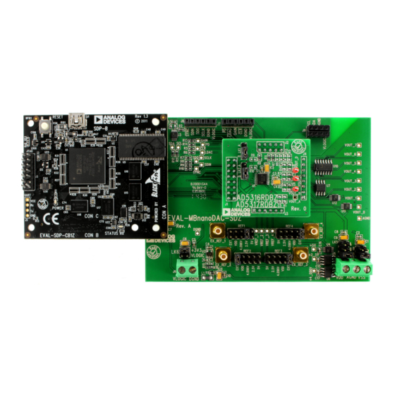
SDP-B
Figure 1.
AD5317R
data sheet, which must be used in
BOARDS
UG-970
AD5317R
EVAL-
Advertisement
Table of Contents

Related Manuals for Analog Devices EVAL-AD5317RDBZ


Summary of Contents for Analog Devices EVAL-AD5317RDBZ
-
Page 1: Features
(DAC). On-board references Various link options The evaluation board is designed to help users quickly prototype PC control in conjunction with Analog Devices, Inc., system AD5317R circuits and reduce design time. The AD5317R demonstration platform (SDP) operates from a single 2.7 V to 5.5 V supply. -
Page 2: Table Of Contents
General Description ................. 1 Evaluation Board Schematics and Artwork ........7 EVAL-AD5317RDBZ, EVAL-MBnanoDAC-SDZ, and SDP-B EVAL-MBnanoDAC-SDZ Motherboard ........7 Boards....................1 EVAL-AD5317RDBZ Daughter Board ........10 Revision History ................2 Ordering Information ..............12 Evaluation Board Hardware ............3 Bill of Materials ................12 Motherboard Power Supplies ............ -
Page 3: Evaluation Board Hardware
EVAL-AD5317RDBZ User Guide UG-970 EVALUATION BOARD HARDWARE MOTHERBOARD POWER SUPPLIES MOTHERBOARD LINK OPTIONS EVAL-MBnanoDAC-SDZ motherboard supports single A number of link options are incorporated in the EVAL- and dual power supplies. MBnanoDAC-SDZ and must be set for the required operating conditions before using the board. -
Page 4: Evaluation Board Software Quick Start Procedures
SDP-B board and the PC. Power up the evaluation board as described in the Motherboard Power Supplies section. From the Start menu, click All Programs, Analog Devices, AD5317R Evaluation Software. If the SDP-B board is not connected to the USB port when the software is launched, a connectivity error displays (see Figure 2). -
Page 5: Software Operation
EVAL-AD5317RDBZ User Guide UG-970 Figure 4. AD5317R Evaluation Software Main Window SOFTWARE OPERATION Power-Down Control Each of the DACs can be powered down individually. Each of the The software for the AD5317R allows the user to program values DACs has an associated selection box allowing the selected DAC to to the input and DAC registers of each DAC individually or operate in normal mode or power-down mode. - Page 6 UG-970 EVAL-AD5317RDBZ User Guide GAIN Control LDAC Mask Register To set the GAIN pin high or low, click the blue progressive Each DAC can be configured to respond to or ignore the LDAC disclosure option on the GAIN SELECT block to access the Gain pin settings in the LDAC Configuration window.
-
Page 7: Evaluation Board Schematics And Artwork
EVAL-AD5317RDBZ User Guide UG-970 EVALUATION BOARD SCHEMATICS AND ARTWORK EVAL-MBnanoDAC-SDZ MOTHERBOARD +3.3V USB_VBUS BEAD 1.6Ω RESET_IN BMODE1 UART_RX UART_TX 100kΩ 24LC32 RESET_OUT SLEEP 4.7µF 0.1µF EXT_VDD EEPROM_A0 WAKE +3.3V 10µF STANDARD CONNECTOR DGND DGND 100kΩ CLK_OUT DGND TMR_C* TMR_D +3.3V... - Page 8 UG-970 EVAL-AD5317RDBZ User Guide +4.096V +2.5V +2.5V +4.096V REF198 V IN VOUT +2_5VREF +5VREF VOUT OUTPUT +4_096VREF SLEEP ADR431BRZ ADR445ARMZ COMP TRIM TRIM 1µF 1µF 1µF REF1 REF2 REF3 REF4 +5VREF +5VREF +5VREF +5VREF +2_5VREF +2_5VREF +2_5VREF +2_5VREF VREF_4 VREF_1...
- Page 9 EVAL-AD5317RDBZ User Guide UG-970 Figure 12. EVAL-MBnanoDAC-SDZ Motherboard Component Placement Figure 13. EVAL-MBnanoDAC-SDZ Motherboard Top Side Routing Rev. A | Page 9 of 13...
-
Page 10: Eval-Ad5317Rdbz Daughter Board
UG-970 EVAL-AD5317RDBZ User Guide Figure 14. EVAL-MBnanoDAC-SDZ Motherboard Bottom Side Routing EVAL-AD5317RDBZ DAUGHTER BOARD 0.1µF 0.1µF VLOGIC DGND 10µF 10µF LDAC SDIN VREF1 SCLK SYNC GAIN VOUT_A J4-1 VOUT_0 SYNC VOUT_A VOUT_0 AGND J4-2 VOUT_1 0Ω VOUT_B J4-3 VOUT_2 GAIN... - Page 11 EVAL-AD5317RDBZ User Guide UG-970 Figure 16. EVAL-AD5317RDBZ Daughter Board Component Placement Figure 17. EVAL-AD5317RDBZ Daughter Board Top Side Routing Figure 18. EVAL-AD5317RDBZ Daughter Board Bottom Side Routing Rev. A | Page 11 of 13...
-
Page 12: Change To Table 6
UG-970 EVAL-AD5317RDBZ User Guide ORDERING INFORMATION BILL OF MATERIALS Table 4. EVAL-MBnanoDAC-SDZ Motherboard Reference Designator Description Supplier/Part Number 1, 2 C1, C6, C7, C9 6.3 V, tantalum capacitor (Case A), 10 µF, ±20% FEC/1190107 C2, C5, C8, C10 50 V, X7R, ceramic capacitor, 0.1 µF, ±10%... - Page 13 By using the evaluation board discussed herein (together with any tools, components documentation or support materials, the “Evaluation Board”), you are agreeing to be bound by the terms and conditions set forth below (“Agreement”) unless you have purchased the Evaluation Board, in which case the Analog Devices Standard Terms and Conditions of Sale shall govern. Do not use the Evaluation Board until you have read and agreed to the Agreement.
Need help?
Do you have a question about the EVAL-AD5317RDBZ and is the answer not in the manual?
Questions and answers