Advertisement
Evaluation Board User Manual
5 Steps To Setup The Evaluation Board...
1. Install AD5282 Software
2. Configure Board and Connect to Parallel Port with
Provided Parallel Cable
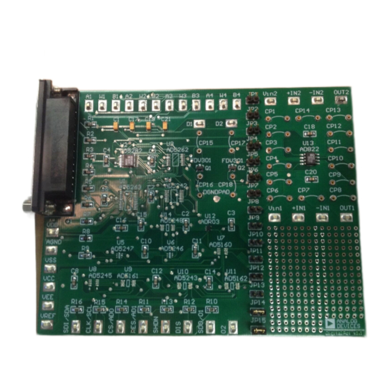
Figure 1. Evaluation Kit Setup
Rev B 11/03/03
256-Position I
Dual, +15V, Digital Potentiometer
3. Open AD5282 Rev A.exe
+5V
GND
No Programming
Skills Required!
1
2
C Compatible
AD5282
4. Provide Power
SupplyOr
Power from Parallel Port
W
B
5. Measure Result
Use
Advertisement
Table of Contents

Subscribe to Our Youtube Channel
Related Manuals for Analog Devices AD5282


Summary of Contents for Analog Devices AD5282
- Page 1 Dual, +15V, Digital Potentiometer AD5282 Evaluation Board User Manual 5 Steps To Setup The Evaluation Board… 1. Install AD5282 Software 3. Open AD5282 Rev A.exe 4. Provide Power SupplyOr Power from Parallel Port 2. Configure Board and Connect to Parallel Port with Provided Parallel Cable 5.
- Page 2 This evaluation board provides the user with a simple and quick solution to evaluate digital potentiometers from Analog Devices. Only one digital pot can be placed on the board at a time. For the user’s convenience, a general purpose opamp, 2.5V voltage reference, and two power MOSFETs are included and can be configured in a variety of flexible configurations.
- Page 3 256-Position I C Compatible Dual, +15V, Digital Potentiometer AD5282 Evaluation Board User Manual ADR03 2.5V Reference VREF DGND Temp Trim CLK/SCL SDI/SDA DGND CS/AD0 CS/AD0 CS/AD0 SPI/I2C CLK/SCL SDI/SDA DGND Vout SDO/NC AD5247 SDI/SDA CLK/SCL SDI/SDA CLK/SCL ADR03 AD5160 0.1u AD5161 0.1u...
- Page 4 Configuring other Components Two Channel Opamp - AD822 Positive Supply To use the same VDD as the AD5282, connect JP6. To use a separate positive supply, connect JP7 and apply positive supply(no more than +5V) to the VCC pad. Negative Supply To use GND, simply connect JP8.
- Page 5 2.5V Voltage Reference – ADR03 By connecting JP5, the voltage reference is connected to the A-terminal of channel-1 of the AD5282. You don’t need to worry about applying VDD because it is hardwired from the same source that is powering the AD5282.
- Page 6 256-Position I C Compatible Dual, +15V, Digital Potentiometer AD5282 Evaluation Board User Manual AD5282 Parallel Port Connection (Information for Visual Basic Program Developers Only) SHDN VDD DIS RES/AD1 CS/AD0 CLK/SCL SDI/SDA DGND SDO/O1 SDA_Read http://www.doc.ic.ac.uk/~ih/doc/par/ 8 output pins accessed via the DATA Port portID = Val("&H"...
Need help?
Do you have a question about the AD5282 and is the answer not in the manual?
Questions and answers