
Related Manuals for Measurement Computing USB-1208HS-4AO


Summary of Contents for Measurement Computing USB-1208HS-4AO
- Page 1 USB-1208HS-4AO High-Speed Analog Input and Digital I/O User's Guide Document Revision 4 July 2014 © Copyright 2014...
- Page 2 © 2014 Measurement Computing Corporation. All rights reserved. No part of this publication may be reproduced, stored in a retrieval system, or transmitted, in any form by any means, electronic, mechanical, by photocopying, recording, or otherwise without the prior written permission of Measurement Computing Corporation.
-
Page 3: Table Of Contents
About this Manual ..........................5 Conventions ................................ 5 Where to find more information ......................... 5 Chapter 1 Introducing the USB-1208HS-4AO ...................... 6 Functional block diagram ........................... 6 Chapter 2 Installing the USB-1208HS-4AO ......................7 What comes with your shipment? ........................7 Hardware .................................. - Page 4 USB-1208HS-4AO User's Guide Environmental ..............................21 Mechanical ............................... 22 Screw terminal connector and pinout ....................... 22 Declaration of Conformity ........................24...
-
Page 5: Preface
Italic text is used for the names of manuals and help topic titles, and to emphasize a word or phrase. Where to find more information Additional information about USB-1208HS-4AO hardware is available on our website at www.mccdaq.com. You can also contact Measurement Computing Corporation by phone, fax, or email with specific questions. Knowledgebase: kb.mccdaq.com... -
Page 6: Introducing The Usb-1208Hs-4Ao
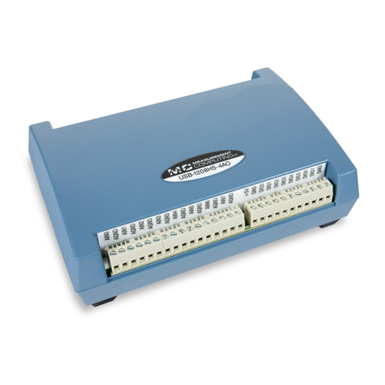
The USB-1208HS-4AO is a USB 2.0 high-speed device supported under popular Microsoft Windows operating systems. The USB-1208HS-4AO is compatible with both USB 1.1 and USB 2.0 ports (although the speed of the module maybe limited when using USB 1.1 ports). -
Page 7: Installing The Usb-1208Hs-4Ao
Refer to the Quick Start Guide for instructions. To connect the USB-1208HS-4AO to your system, turn your computer on, and connect the USB cable to a USB port on your computer or to an external USB hub connected to your computer. The USB cable provides power and communication to the USB-1208HS-4AO. -
Page 8: Calibrating The Usb-1208Hs-4Ao
Installing the USB-1208HS-4AO Caution! Do not disconnect any device from the USB bus while the computer is communicating with the device, or you may lose data and/or your ability to communicate with the USB-1208HS-4AO.. If the Status LED turns off The Status LED turns off if communication is lost between the device and the computer. -
Page 9: Functional Details
FIFO buffer on the device until you stop the scan. The FIFO buffer is serviced in blocks as the data is transferred from the USB-1208HS-4AO FIFO buffer to the memory buffer on your computer. -
Page 10: Screw Terminals
USB-1208HS-4AO User's Guide Functional Details Screw terminals The differential mode pinout is shown in Figure 3. Figure 3. Differential mode pinout The single-ended mode pinout is shown in Figure 4. Figure 4. Single-ended mode pinout Use 16 AWG to 30 AWG for signal connections. -
Page 11: Usb Connector
The USB connector provides +5 V power and communication. No external power supply is required. Activity LED The Activity LED indicates the communication status of the USB-1208HS-4AO. It blinks when data is transferred, and is off when the device is not communicating. This LED uses up to 10 mA of current and cannot be disabled. -
Page 12: Analog Output
Each channel can be software-paced at rates up to 5,000 updates per second (system-dependent), or hardware- paced at rates up to 1 MS/s. Each analog output on the USB-1208HS-4AO has a fixed ±10 V output range. The outputs default to 0 V at power up. -
Page 13: Digital I/O
Each of the 16 DIO bits on the USB-1208HS-4AO has a 47 kΩ pull-up/pull-down resistor. To configure these bits for either a +5 V pull-up or a 0 V pull-down option, you must open the USB-1208HS-4AO case to access the three-pin jumper labeled W34. -
Page 14: Counter Input
USB-1208HS-4AO User's Guide Functional Details Figure 9. Location of W34 jumper (default pull-down setting shown) Figure 10. Pull-down and pull-up configurations Replace the top section of the case, and then fasten it to the bottom section with the four screws. -
Page 15: Trigger Input
USB-1208HS-4AO User's Guide Functional Details Both the period and time delay ranges are 50 ns to 107.4 seconds. Figure 11. USB-1208HS-4AO PWM timer channel Trigger input TRIG connection is an external digital trigger input. The trigger mode is software selectable for: ... -
Page 16: Chapter 4 Specifications
Chapter 4 Specifications All specifications are subject to change without notice. Typical for 25 °C unless otherwise specified. Specifications in italic text are guaranteed by design. Analog input Table 1. Analog input specifications Parameter Condition Specification A/D converter Analog Devices AD7329 13-bit successive approximation type Input ranges Software-selectable... - Page 17 0 – 10 V (SE mode) ±3.29 typ, ±5.13 max Table 3 summarizes the noise performance for the USB-1208HS-4AO. Noise distribution is determined by gathering 50 kS with inputs tied to ground at the user connector. Samples are gathered at the maximum specified sample rate of 1 MS/s.
-
Page 18: Analog Output
USB-1208HS-4AO User's Guide Specifications Analog output Table 5. Analog output specifications Parameter Condition Specification D/A converter Texas Instruments DAC7553 Number of channels 4 independent Resolution 12 bits Output range Calibrated ±10 V Uncalibrated ±10.2 V Output transient Host PC is reset, powered on, suspended, or Duration: 3 ms typ a reset command is issued to device. -
Page 19: External Trigger
USB-1208HS-4AO User's Guide Specifications External trigger Table 7. External trigger specifications Parameter Specification Trigger source TRIG input Trigger mode Software-selectable for edge or level sensitive, rising or falling edge, high or low level. Power on default is edge sensitive, rising edge. -
Page 20: Counters
USB-1208HS-4AO User's Guide Specifications Counters Table 9. Counter specifications Parameter Specification Counter terminal names CTR0, CTR1 Counter type Event counter Number of channels Schmitt trigger, 33 Ω series resistor, 47 kΩ pull-down to ground Input type Schmitt trigger hysteresis 0.4 V to 1.2 V Input high voltage 2.2 V min... -
Page 21: Power
Subminiature Surface Mount Fuse. Spare fuse mounted in holder on PCB. This is the total current consumption for the USB-1208HS-4AO, including +5 V, digital output and Note 1: analog output currents (if supported). Output voltage range assumes input power is within specified limits. -
Page 22: Mechanical
USB-1208HS-4AO User's Guide Specifications Mechanical Table 15. Mechanical specifications Parameter Specification Dimensions (L × W × H) 5.00 × 3.53 × 1.40 in. (127 × 89.9 × 35.6 mm) Screw terminal connector and pinout Table 16. Connector specifications Parameter Specification... - Page 23 USB-1208HS-4AO User's Guide Specifications Table 18. Differential mode pinout Signal name Signal name AIN0 + AOUT0 AGND AOUT1 AIN0 - AGND AGND AOUT2 AIN1 + AOUT3 AGND AGND AIN1 - AICKI AGND AICKO AIN2 + AOCKI AGND AOCKO AIN2 -...
-
Page 24: Declaration Of Conformity
Norton, MA 02766 Category: Electrical equipment for measurement, control and laboratory use. Measurement Computing Corporation declares under sole responsibility that the products USB-1208HS-4AO to which this declaration relates is in conformity with the relevant provisions of the following standards or other documents: EC EMC Directive 2004/108/EC: General Requirements, EN 61326-1:2006 (IEC 61326-1:2005). - Page 25 Measurement Computing Corporation 10 Commerce Way Suite 1008 Norton, Massachusetts 02766 (508) 946-5100 Fax: (508) 946-9500 E-mail: info@mccdaq.com www.mccdaq.com...
Need help?
Do you have a question about the USB-1208HS-4AO and is the answer not in the manual?
Questions and answers