Table of Contents
Advertisement
Quick Links
Download this manual
See also:
User Manual
Advertisement
Table of Contents

Related Manuals for Measurement Computing USB-1208LS


Summary of Contents for Measurement Computing USB-1208LS
- Page 1 USB-1208LS Analog and Digital I/O User's Guide Document Revision 4A June 2015 © Copyright 2015...
- Page 2 Other product and company names mentioned herein are trademarks or trade names of their respective companies. © 2015 Measurement Computing Corporation. All rights reserved. No part of this publication may be reproduced, stored in a retrieval system, or transmitted, in any form by any means, electronic, mechanical, by photocopying, recording, or otherwise without the prior written permission of Measurement Computing Corporation.
-
Page 3: Table Of Contents
Preface About this User's Guide ........................5 Conventions in this user's guide ......................... 5 Where to find more information ......................... 5 Chapter 1 Introducing the USB-1208LS........................ 6 Functional block diagram ........................... 6 Chapter 2 Installing the USB-1208LS........................7 Unpacking................................7 Installing the software ............................ - Page 4 USB-1208LS User's Guide Declaration of Conformity ........................24...
-
Page 5: Preface
Preface About this User's Guide This user's guide describes the Measurement Computing USB-1208LS data acquisition device and lists device specifications. Conventions in this user's guide For more information Text presented in a box signifies additional information related to the subject matter. -
Page 6: Introducing The Usb-1208Ls
I/O connections are made to the device screw terminals. The USB-1208LS device is compatible with both USB 1.1 and USB 2.0 ports. The speed of the device may be limited when using a USB 1.1 port due to the difference in transfer rates on the USB 1.1 versions of the protocol (low-speed and full-speed). -
Page 7: Installing The Usb-1208Ls
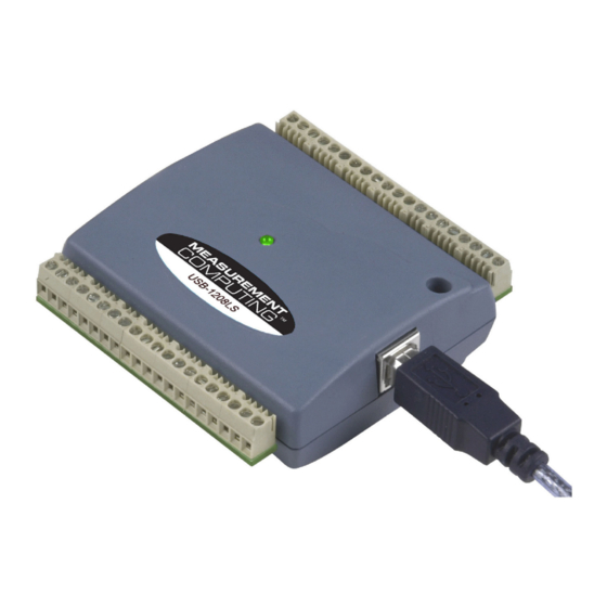
Before installing the device, run Windows Update to update your system with the latest HID and USB drivers. To connect the USB-1208LS to your system, turn your computer on, and connect the USB cable to a USB port on your computer or to an external USB hub that is connected to your computer. The USB cable provides power and communication to the device. -
Page 8: Chapter 3 Functional Details
BURSTIO mode In BURSTIO mode, you acquire data using the full capacity of the USB-1208LS 4 k sample FIFO. You can initiate a single acquisition sequence of up to 4096 samples channels by either a software command or an external hardware trigger. -
Page 9: Usb Connector
5V. No external power supply is required. The LED on the front of the housing indicates the communication status of the USB-1208LS. It uses up to 5 mA of current and cannot be disabled. The table below defines the function of the LED. -
Page 10: Signal Connections
USB-1208LS User's Guide Functional Details The single-ended mode pinout is shown in Figure 4. Figure 4. Single-ended mode pinout Signal connections Analog inputs You can connect up to eight analog input connections to the screw terminal containing pins 1 to 20 (... - Page 11 USB-1208LS User's Guide Functional Details In differential mode, the following two requirements must be met for linear operation: Any analog input must remain in the −10V to +20V range with respect to ground at all times. The maximum differential voltage on any given analog input pair must remain within the selected voltage ...
-
Page 12: Digital I/O
BIP10V BIP1V When a scan begins with the gain queue enabled, the USB-1208LS reads the first element, sets the appropriate channel number and range, and then acquires a sample. The properties of the next element are then retrieved, and another sample is acquired. This sequence continues until all elements in the gain queue have been selected. -
Page 13: Trigger Input
With all outputs at their maximum output current, the total current requirement of the USB +5 V is: (USB-1208LS @ 20 mA) + (16 DIO @ 2.5 mA ea) + (2 AO @ 30 mA ea ) = 120 mA For an application running on a PC or powered hub, the maximum available excess current is 500 mA−120 mA... -
Page 14: Accuracy
The USB-1208LS offset error is measured at mid-scale. Ideally, a zero volt input should produce an output code of 2048. Any deviation from this is an offset error. Figure 10 shows the USB-1208LS transfer function with an offset error. The typical offset error specification on the ±10 V range is ±9.77 mV. Offset error affects all codes... - Page 15 Figure 11. ADC Transfer function with gain error For example, the USB-1208LS exhibits a typical calibrated gain error of ±0.2% on all ranges. For the ±10 V range, this would yield 10 V × ±0.002 = ±20 mV. This means that at full scale, neglecting the effect of offset for the moment, the measurement would be within 20 mV of the actual value.
- Page 16 USB-1208LS User's Guide Functional Details Combining these two error sources in Figure 12, we have a plot of the error band of the USB-1208LS for the ±10 V range. This is a graphical version of the typical accuracy specification of the product.
-
Page 17: Mechanical Drawings
USB-1208LS User's Guide Functional Details Mechanical drawings Figure 13. Circuit board (top) and enclosure dimensions... -
Page 18: Chapter 4 Specifications
Chapter 3 Specifications All specifications are subject to change without notice. Typical for 25°C unless otherwise specified. Specifications in italic text are guaranteed by design. Analog input Table 1. Analog input specifications Parameter Conditions Specification A/D converter type Successive approximation type Input voltage range for linear operation, CHx to GND ±10 V max... -
Page 19: Analog Output
USB-1208LS User's Guide Specifications Table 2. Accuracy, differential mode Range Accuracy (LSB) ±20 V ±10 V ±5 V ±4 V ±2.5 V 12.1 ±2 V 14.1 ±1.25 V 20.1 ±1 V 24.1 Table 3. Accuracy, single-ended mode Range Accuracy (LSB) ±10 V... -
Page 20: Digital Input/Output
USB-1208LS User's Guide Specifications Digital input/output Table 7. DIO specifications Parameter Specification Digital type 82C55 Number of I/O 16 (Port A0 through A7, Port B0 through B7 Configuration 2 banks of 8 Pull up/pull-down configuration All pins pulled up to Vs through 47 kΩ resistors (default). Positions available for pull down to ground. -
Page 21: Non-Volatile Memory
450 mA min, 500 mA max Connected to bus-powered hub 50 mA min, 100 mA max This is the total current requirement for the USB-1208LS which includes up to 5 mA for the status Note 5: LED. Self-powered refers to USB hubs and hosts with a power supply. Bus-powered refers to USB hubs and Note 6: hosts without their own power supply. -
Page 22: Mechanical
USB-1208LS User's Guide Specifications Mechanical Table 14. Mechanical specifications Parameter Specification Dimensions (L × W × H) 79 × 82 × 27 mm (3.10 × 3.20 × 1.05 in.) USB cable length 3 m (9.84 ft) max User connection length 3 m (9.84 ft) max... - Page 23 USB-1208LS User's Guide Specifications 8-channel single-ended mode Signal Name Signal Name CH0 IN Port A0 CH1 IN Port A1 Port A2 CH2 IN Port A3 CH3 IN Port A4 Port A5 CH4 IN Port A6 CH5 IN Port A7 CH6 IN...
- Page 24 Norton, MA 02766 Category: Electrical equipment for measurement, control and laboratory use. Measurement Computing Corporation declares under sole responsibility that the product USB-1208LS to which this declaration relates is in conformity with the relevant provisions of the following standards or other documents: EC EMC Directive 2004/108/EC: General Requirements, EN 61326-1:2006 (IEC 61326-1:2005).
- Page 25 Measurement Computing Corporation 10 Commerce Way Suite 1008 Norton, Massachusetts 02766 (508) 946-5100 Fax: (508) 946-9500 E-mail: info@mccdaq.com www.mccdaq.com...
Need help?
Do you have a question about the USB-1208LS and is the answer not in the manual?
Questions and answers