
Related Manuals for Measurement Computing USB-1608G-OEM


Summary of Contents for Measurement Computing USB-1608G-OEM
- Page 1 USB-1608G-OEM High-speed Multifunction DAQ User's Guide Document Revision 2 January 2015 © Copyright 2015...
- Page 2 © 2015 Measurement Computing Corporation. All rights reserved. No part of this publication may be reproduced, stored in a retrieval system, or transmitted, in any form by any means, electronic, mechanical, by photocopying, recording, or otherwise without the prior written permission of Measurement Computing Corporation.
-
Page 3: Table Of Contents
What you will learn from this user's guide ......................5 Conventions in this user's guide ......................... 5 Where to find more information ......................... 5 Chapter 1 Introducing the USB-1608G-OEM ......................6 Functional block diagram ........................... 6 Chapter 2 Installing the USB-1608G-OEM ......................7 Unpacking................................ - Page 4 USB-1608G-OEM User's Guide Counter ................................20 Timer ................................21 Memory ................................21 Power ................................21 USB .................................. 21 Environmental ..............................22 Mechanical ............................... 22 Header connector .............................. 22 Pin orientation ..................................22 Differential mode pinout ..............................23 Single-ended mode pinout ...............................24...
-
Page 5: Preface
Italic text is used for the names of manuals and help topic titles, and to emphasize a word or phrase. Where to find more information Additional information about USB-1608G-OEM hardware is available on our website at www.mccdaq.com. You can also contact Measurement Computing Corporation by phone, fax, or email with specific questions. Knowledgebase: kb.mccdaq.com... -
Page 6: Introducing The Usb-1608G-Oem
Header connectors for field wiring connections The USB-1608G-OEM device is compatible with both USB 1.1 and USB 2.0 ports. The speed of the device may be limited when using a USB 1.1 port due to the difference in transfer rates on the USB 1.1 versions of the protocol (low-speed and full-speed). -
Page 7: Installing The Usb-1608G-Oem
Installing on a Windows platform Install the software before you install your device A driver needed to run the USB-1608G-OEM is installed when you install the software. Therefore, you need to install the software package you plan to use before you install the hardware. -
Page 8: Calibrating The Hardware
Calibrating the hardware Factory calibration The Measurement Computing Manufacturing Test department performs the initial factory calibration. Contact Measurement Computing for details about how to return your device and have it calibrated to the factory specifications. Field calibration The USB-1608G-OEM supports field calibration. Calibrate the device using InstaCal whenever the ambient temperature changes by more than ±10 °C from the last field calibration. -
Page 9: Chapter 3 Functional Details
Functional Details Analog input modes The USB-1608G-OEM can acquire analog input data in two basic modes – software paced and hardware paced. Software paced You can acquire one analog sample at a time in software paced mode. You initiate the A/D conversion with a software command. -
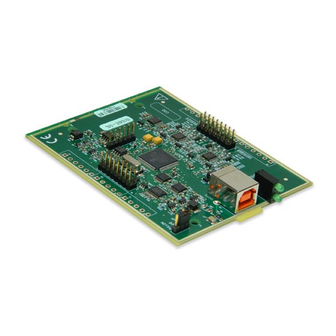
Page 10: Board Components
USB-1608G-OEM User's Guide Functional Details Board components Board components are shown in Figure 3. Note that each screw terminal location is unpopulated. Screw terminal (unpopulated) Pull-up/down jumper W1 Header connector W4 Status LED (top) and Activity LED (bottom) Header connector W6... - Page 11 USB-1608G-OEM User's Guide Functional Details Differential mode pinout Signal Name Description Signal Name Description CH0H Channel 0 HI CH7L Channel 7 LO CH0L Channel 0 LO CH7H Channel 7 HI AGND Analog ground AGND Analog ground CH1H Channel 1 HI...
-
Page 12: Signal Connections
USB-1608G-OEM User's Guide Functional Details Single-ended mode pinout Signal Name Description Signal Name Description Channel 0 CH15 Channel 15 Channel 8 Channel 7 AGND Analog ground AGND Analog ground Channel 1 CH14 Channel 14 Channel 9 Channel 6 AGND Analog ground... -
Page 13: External Clock I/O
For more information about analog input connections, refer to the Guide to Signal Connections (this document is available on our web site at www.mccdaq.com/signals/signals.pdf). External clock I/O The USB-1608G-OEM provides one external clock input ( ) and one external clock output ( ) for... -
Page 14: Digital I/O
USB-1608G-OEM User's Guide Functional Details Digital I/O You can connect up to eight digital I/O lines to through . Each digital channel is individually DIO0 DIO7 configurable for input or output. The digital I/O terminals can detect the state of any TTL-level input. Refer to the schematic shown in Figure 5. -
Page 15: Counter Input
USB-1608G-OEM User's Guide Functional Details Retrigger mode Retrigger mode lets you set up repetitive analog input or output trigger events. The trigger is automatically re- armed after it is activated. Use software to set the A/D or D/A trigger count (the number of samples you want per trigger). -
Page 16: Mechanical Drawings
USB-1608G-OEM User's Guide Functional Details Mechanical drawings Figure 9. USB-1608G-OEM circuit board dimensions... -
Page 17: Chapter 4 Specifications
Chapter 4 Specifications All specifications are subject to change without notice. Typical for 25 °C unless otherwise specified. Specifications in italic text are guaranteed by design. Analog input Table 1. General analog input specifications Parameter Condition Specification A/D converter type Successive approximation ADC resolution 16 bits... -
Page 18: Accuracy
USB-1608G-OEM User's Guide Specifications Accuracy Analog input DC voltage measurement accuracy Table 2. DC Accuracy components and specifications. All values are (±) Absolute Gain Offset accuracy at temperature temperature Gain error Offset error INL error Full Scale coefficient coefficient Range (% of reading) (µV) -
Page 19: Digital Input/Output
USB-1608G-OEM User's Guide Specifications Digital input/output Table 6. Digital input/output specifications Parameter Specification Digital type CMOS Number of I/O Configuration Each bit may be configured as input (power on default) or output The port has 47 kΩ resistors configurable as pull-ups or pull-downs (default) via Pull-up configuration internal jumper (W1). -
Page 20: External Clock Input/Output
USB-1608G-OEM User's Guide Specifications External clock input/output Table 8. External clock I/O specifications Parameter Specification Terminal names AICKI, AICKO Terminal types AICKI: Input, active on rising edge AICKO: Output, power on default is 0 V, active on rising edge Terminal descriptions... -
Page 21: Timer
USB-1608G-OEM User's Guide Specifications Timer Table 10. Timer specifications Parameter Specification Terminal name Timer type PWM output with count, period, delay, and pulse width registers Output value Default state is idle low with pulses high, Software-selectable output invert Internal clock frequency... -
Page 22: Environmental
USB-1608G-OEM User's Guide Specifications Environmental Table 14. Environmental specifications Parameter Specification Operating temperature range 0 °C to 55 °C max Storage temperature range –40 °C to 85 °C max Humidity 0% to 90% non-condensing max Mechanical Table 15. Mechanical specifications... -
Page 23: Differential Mode Pinout
USB-1608G-OEM User's Guide Specifications Differential mode pinout Table 17. 8-channel differential mode pinout Signal Name Description Signal Name Description CH0H Channel 0 HI CH7L Channel 7 LO CH0L Channel 0 LO CH7H Channel 7 HI AGND Analog ground AGND Analog ground... -
Page 24: Single-Ended Mode Pinout
USB-1608G-OEM User's Guide Specifications Single-ended mode pinout Table 18. 16-channel single-ended mode pinout Signal Name Description Signal Name Description Channel 0 CH15 Channel 15 Channel 8 Channel 7 AGND Analog ground AGND Analog ground Channel 1 CH14 Channel 14 Channel 9... - Page 25 Measurement Computing Corporation 10 Commerce Way Suite 1008 Norton, Massachusetts 02766 (508) 946-5100 Fax: (508) 946-9500 E-mail: info@mccdaq.com www.mccdaq.com...
Need help?
Do you have a question about the USB-1608G-OEM and is the answer not in the manual?
Questions and answers