Table of Contents
Advertisement
Quick Links
Advertisement
Table of Contents

Related Manuals for Atlona Gain 120


Summary of Contents for Atlona Gain 120
- Page 1 Stereo / Mono Audio Power Amplifier 120 Watts Atlona Manuals AT-GAIN-120 Audio...
- Page 2 Version Information Version Release Date Notes 4/18 Initial release AT-GAIN-120...
- Page 3 Welcome to Atlona! Thank you for purchasing this Atlona product. We hope you enjoy it and will take an extra few moments to register your new purchase. Registration only takes a few minutes and protects this product against theft or loss. In addition, you will receive notifications of product updates and firmware.
- Page 4 Atlona requires that products returned are properly packed, preferably in the original carton, for shipping. Cartons not bearing a return authorization or case number will be refused. Atlona, at its sole discretion, reserves the right to reject any products received without advanced authorization. Authorizations can be requested by calling 1-877-536-3976 (US toll free) or 1-408- 962-0515 (US/international) or via Atlona’s website at www.atlona.com.
- Page 5 Damage, deterioration or malfunction resulting from the installation or removal of this product from any installation, any unauthorized tampering with this product, any repairs attempted by anyone unauthorized by Atlona to make such repairs, or any other cause which does not relate directly to a defect in materials and/or workmanship of this product.
- Page 6 Important Safety Information The lightning flash with arrowhead symbol, within an equilateral triangle, is intended to alert the user to the presence of uninsulated “dangerous voltage” within the product’s enclosure that may be of sufficient magnitude to constitute a risk of electric shock to persons. Das Symbol des Blitzzeichens innerhalb eines gleichseitigen Dreiecks soll den Benutzer davor warnen, dass innerhalb des Gehäuses gefährlich hohe Spannung an berührbaren Teilen anliegt.
- Page 7 The information bubble is intended to alert the user to helpful or optional opera- product. tional instructions in the literature accompanying the product. 11. Only use attachments/accessories specified by Atlona. 1. Read these instructions. 12. To reduce the risk of electric shock and/or damage 2. Keep these instructions.
-
Page 8: Table Of Contents
Table of Contents Introduction Features Package Contents Panel Description Installation Audio Connectors ANALOG IN / LINE OUT 4 / 8 Ω OUT 70V / 100V OUT Trigger Connection Instructions Connection Diagram Basic Operation IP Configuration Using the Rear Panel Using Commands Using the Web GUI LED Indicators Power Modes... -
Page 9: Introduction
In addition to the amplified speaker output, a line level audio output allows the incoming audio to be fed into an additional amplifier or audio system. The Gain 120 is controllable via TCP/IP or external trigger, and can be integrated with Atlona AV switchers and HDBaseT™... -
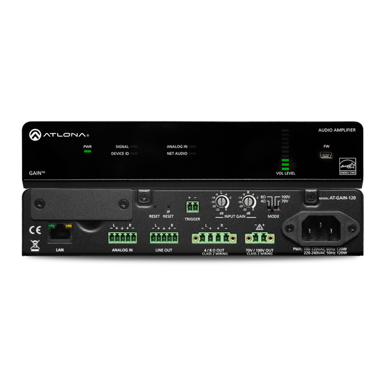
Page 10: Panel Description
Panel Description AUDIO AMPLIFIER AUDIO AMPLIFIER SIGNAL ANALOG IN DEVICE ID NET AUDIO SIGNAL ANALOG IN DEVICE ID NET AUDIO GAIN VOL LEVEL GAIN VOL LEVEL Front 100V AT-GAIN-120 MODEL: 100V AT-GAIN-120 MODEL: RESET RESET TRIGGER INPUT GAIN MODE RESET RESET TRIGGER INPUT GAIN MODE... -
Page 11: Installation
Installation Audio Connectors The AT-GAIN-120 provides two audio ports which provide analog audio input and output. The ANALOG IN port can be used to connect an audio digital signal processor (DSP) or other audio source device. Balanced or unbalanced wiring is supported. The LINE OUT port can be used to connect an audio output device or daisy-chain to another amplifier. -
Page 12: 70V / 100V Out
Installation 70V / 100V OUT Connect a distributed speaker system to the included 2-pin captive screw connector, then connect the terminal block to the 70V / 100V OUT port. When connecting program / stereo speakers, set the MODE switch to either 70V or 100V, depending upon the speakers. Trigger The AT-GAIN-120 provides a TRIGGER port allowing the AT-GAIN-120 to be connected to an occupancy sensor. -
Page 13: Connection Instructions
Network Audio Card Installation (page 38) for more information before continuing with the following instructions. This network card is sold separately and is available from Atlona. 1. Connect an analog audio source, using the included 5-pin captive screw connector, to the AUDIO IN port. -
Page 14: Connection Diagram
Installation Connection Diagram r ic R SY R SY r ic R SY R SY Program Speakers ri c r ic R SY R SY Distributed Speakers r ic ri c R SY R SY PL IFI DI O L LE DI O T AU VI CE... -
Page 15: Basic Operation
Basic Operation IP Configuration The AT-GAIN-120 is shipped with DHCP enabled. Once connected to a network, the DHCP server (if available), will automatically assign an IP address to the unit. Execute the arp -a command at the Windows command line or use an IP scanner to locate the AT-GAIN-120 on the network. -
Page 16: Using Commands
Basic Operation Using Commands Use the IPStatic and IPDHCP commands to switch between DHCP and static IP mode using Telnet. Refer to the Application Programmers Interface documentation for more information. All commands and their arguments are case-sensitive. • Setting static IP mode 1. -
Page 17: Using The Web Gui
1. Open the desired web browser and enter the IP address of the AT-GAIN-120. 2. Log in, using the required credentials. The factory-default username and password are listed below: Username: admin Password: Atlona 3. Click the Network tab, located on the side menu bar. •... - Page 18 Basic Operation 5. The following message box will be displayed: 6. Click OK to accept the changes or click Cancel to abort changes and return to the Network page. AT-GAIN-120...
-
Page 19: Led Indicators
Basic Operation LED Indicators The LED indicators on the front panel, provide information on the current state of the AT-GAIN-120. Refer to the table below for more information. AUDIO AMPLIFIER SIGNAL ANALOG IN DEVICE ID NET AUDIO GAIN VOL LEVEL LED Indicator State Description... -
Page 20: Power Modes
2. Log in, using the required credentials. The factory-default username and password are listed below: Username: admin Password: Atlona 3. Click the Control tab, located on the side menu bar. The Control Settings section will be displayed. Powering On or Off Click the OFF option to power-off the AT-GAIN-120. -
Page 21: Hibernation Mode
• Pull the trigger high using a control system such as Atlona Velocity. Note that even if the Unit Trigger option is set to DISABLE, this method will still wake the AT-GAIN-120. -
Page 22: Network Audio
NOTE: The AT-GAIN-120 was tested using Audinate Dante Controller software v4.0.6.5 and Java v1.8.0. Atlona recommends using Audinate Dante Controller software v4.0.6.5 or higher. 2. Make sure that an Ethernet cable is connected from the INPUT port on the rear panel to the network. -
Page 23: Enabling Aes67 Support
Basic Operation 4. Click the icon, next to the NetAudio-xxxxx card, under Dante Receivers, to view the channels. The AT- GAIN-NET audio card has a maximum of two channels of audio. Refer to the Dante Controller User Guide for details on operation. Click to expand Enabling AES67 Support In order to route AES67 audio over IP, both the transmitter and receiver must support AES67 and have this option... - Page 24 Basic Operation 2. A separate window will open. Click the AES67 tab. 3. Click the New drop-down list and select Enabled. 4. A message box will be displayed prompting to confirm AES67 is to be enabled. Click Yes. 5. Another message box will be displayed. In order for AES67 to be enabled, the card must be rebooted. Click Yes to reboot the network card.
-
Page 25: Volume Control
Basic Operation Volume Control Output audio level is controlled hrough the built-in web GUI. Volume control only affects the 4 / 8 Ω OUT and 70V / 100V OUT ports. Adjusting the audio output volume does not affect the LINE OUT port, as this port is a fixed-level output. -
Page 26: The Web Gui
The Web GUI Introduction to the Web GUI The AT-GAIN-120 includes a built-in web GUI. Atlona recommends that the web GUI be used to set up the AT-GAIN-120, as it provides intuitive management of all features. The AT-GAIN-120 is shipped with DHCP enabled. Once connected to a network, the DHCP server will automatically assign an IP address to the unit. -
Page 27: Menu Bar
The Web GUI 7. The Status page will be displayed. 8. To logout of the web GUI at any time, click Logout on the side menu bar. Once logged out, the AT-GAIN-120 will display the login screen. Menu Bar The window on the left side of the screen is the menu bar. The menu system is divided into three sections: Home, Settings, and Configuration. -
Page 28: Status Page
The Web GUI Status page Download Log Status (progress bar) Click this button to download a log of command events Displays the status of saving and loading system settings to the computer’s hard disk. files. Model Browse The SKU of this product. Click this button to select the desired system settings file. -
Page 29: Firmware Page
The Web GUI Firmware page Current Firmware The current firmware version installed. Status (progress bar) Displays the status of loading new firmware during a firmware update procedure. Browse Click this button to select the firmware file. Click the Load button to begin the update procedure. Refer to Updating the Firmware (page 34) for more information. -
Page 30: Network Page
The Web GUI Network page After pressing the Save button, a reboot message will appear at the top of the web GUI. The AT-GAIN-120 must be rebooted when any of the network settings have changed. DHCP Hostname Click the ON button to enable DHCP. Click the OFF Enter the desired hostname in this field. -
Page 31: Control Page
The Web GUI Control page Power Click the ON button to power-on the AT-GAIN-120. Click the OFF button to power-off the unit. Auto Power Down Enables or disables auto power down mode. Refer to Auto Power Down mode (page 20) for more information. -
Page 32: Users Page
Enter the password for the administrator in this field. Special characters (e.g. #, %, @, &, etc.) are not permitted. Change Admin Password • Old password Enter the current password in this field. The default password is Atlona. • New Password Enter the new password in this field. -
Page 33: Audio Page
Input Selection Click this drop-down list to select the audio input: Analog or Net Audio. The Net Audio selection will only be available if the optional AT-GAIN-NET card is installed. This card is available from Atlona. Output Status Displays the current output impedance setting. -
Page 34: Appendix
2. Type the IP address of the AT-GAIN-120 into the web browser, as shown in the example below. 3. The login screen will be displayed. Login using the username and password. The default login credentials are: Username: admin Password: Atlona AT-GAIN-120... - Page 35 Appendix 4. Click Status in the menu bar on left side of the screen. 5. Click the Save button. 6. The Save As dialog box will be displayed. Select the folder where the file will be saved. Click the Save button to save the file.
-
Page 36: Usb
• Computer with USB port 1. Download the latest firmware from the Atlona web site. 2. Disconnect the power from the AT-GAIN-120. 3. Connect the USB cable from the FW port on the front panel to the computer with the firmware. -
Page 37: Rack Mount Installation
The AT-GAIN-120 can be mounted in different ways, based on the number of units that are being installed. When installed into a standard 19” rack, the AT-RACK-1RU will need to be purchased from atlona.com. The AT-RACK-1RU can be used to either mount a single AT-GAIN-120 unit or it can be used to mount multiple half- rack Atlona products, such as a AT-GAIN-120 and a AT-UHD-SW-510W. -
Page 38: Network Audio Card Installation
Appendix Network Audio Card Installation The AT-GAIN-NET is an optional audio card which allows Dante and AES67 audio streams to be used with the AT- GAIN-120. Follow the instructions below to install the AT-GAIN-NET audio card. WARNING: To prevent the risk of electrocution or electric shock, always disconnect the power cord from the AT-GAIN-120 before installing or removing the AT-GAIN-NET network card. - Page 39 Appendix 4. Locate the plastic guides on either side of the expansion slot. Upper Rail Plastic Guides Lower Rail 5. Carefully position the card between the upper and lower rail of each guide, and gently push the AT-GAIN-NET network card forward, until it locks in place. The card will make a small snapping sound, once the card is in place.
- Page 40 Appendix 6. Locate the included AT-GAIN-NET faceplate with the INPUT port and install the faceplate using the screws from Step 2, as shown below. Do not over-tighten the screws using high-torque devices, as this may cause damage to the screws or the faceplate assembly. Included AT-GAIN-NET Faceplate 7.
-
Page 41: Default Settings
Auto Power Down Enabled Auto Power Down Timer (min) Hibernation Disabled Unit Trigger Disabled Blink Disabled Users Admin username admin Admin password Atlona Audio Input Selection Analog Equalization bands 40 Hz 150 Hz 500 Hz 2 kHz 10 kHz Volume AT-GAIN-120... -
Page 42: Specifications
Appendix Specifications Connectors, Controls, and Indicators INPUT 1 - RJ45 (AT-GAIN-NET network audio card, only), 100 Mbps 1 - RJ45 ANALOG IN 1 - 5-pin captive screw, balanced: 20 k Ω, unbalanced: 10 kΩ LINE OUT 1 - 5-pin, 3.5mm TRIGGER 1 - 2-pin captive screw 4 / 8 Ω... - Page 43 Appendix Audio Performance Frequency Response 20 Hz - 20 kHz, ±2 dB @ 4 Ω load THD + N < 0.1% @ 1kHZ, 3 db below clipping > 90 dBA WTD Damping Factor < 90 @ 8 Ω Amplifier Type Class D Temperature Fahrenheit...
-
Page 44: Index
Index Appendix LED indicators Audio connectors distributed speakers impedance Mode switch Auto power-down. See Power modes: auto power- settings down Network audio Configuration AES67 support See IP configuration card installation Connection Dante configuration diagram instructions Contents package Operating notes Customer support Panel descriptions Default setttings Password Description... - Page 45 Index Volume adjusting 25, 33 Warranty Web GUI AT-GAIN-120...
- Page 46 • 408.962.0515 • 877.536.3976 © 2018 Atlona Inc. All rights reserved. “Atlona” and the Atlona logo are registered trademarks of Atlona Inc. All other brand names and trademarks or registered trademarks are the property of their respective owners. Pricing, specifications and availability...
Need help?
Do you have a question about the Gain 120 and is the answer not in the manual?
Questions and answers