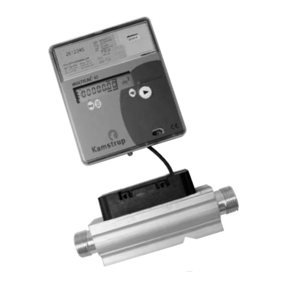
Kamstrup MULTICAL 41 Installation Manual
Water meter
Hide thumbs
Also See for MULTICAL 41:
- Installation and user manual (17 pages) ,
- Technical description (44 pages)
Summary of Contents for Kamstrup MULTICAL 41
- Page 1 Installation MULTICAL 41 Water Meter ® English Kamstrup A/S Industrivej 28, Stilling DK-8660 Skanderborg TEL: +45 89 93 10 00 FAX: +45 89 93 10 01 info@kamstrup.com www.kamstrup.com...
-
Page 2: General Information
1. General information Please read these instructions before installing the heat me- ter. Kamstrup’s guarantee obligations do not apply in case of incorrect installation. Please note the following installation requirements: Gland meters Max. 16 bar 1.1 MID designations Rated operation conditions/measuring ranges: Temperature of medium in flow sensor: 0.1°C…30°C... - Page 3 2. Information codes “E” MULTICAL 41 constantly monitors a number of important func- ® tions. If a serious error occurs in the metering system or in the installation, an “E” appears in the left side of the display and an information code can be read by activating the front key until an “E”...
- Page 4 3. Mounting of flow part Before mounting the flow part (flow sensor), flush the system thoroughly and remove protection plugs/plastic membranes from the flow sensor. The flow direction is indicated by an arrow on the side of the flow sensor. There are no requirements for straight inlet, but we recommend a straight inlet of 3…5 ×...
- Page 5 3.1 Mounting the flow sensor The flow sensor can be mounted vertically, horizontally or at an angle. The flow sensor can be turned upwards to max. 45° and downwards to max. 90° in relation to the pipe axis. Do not mount the flow sensor with the plastic box upwards.
-
Page 6: Mounting The Calculator
4. Mounting the calculator 4.1 Mounting MULTICAL 41 must be mounted on the wall due to the risk ® of condensation in the electronics part. Use the fittings as a template for marking-out and drill 2 pcs. holes of 6 mm in the wall. After mounting the calculator is sealed with seal and thread. -
Page 7: Power Supply
The battery cannot be and must neither be charged nor short- circuited. Used batteries must be handed in for approved de- struction e.g. at Kamstrup A/S. 5.2 Mains modules The modules are in protection class II and are connected via a two- wire cable (without earth) through the cable bush of the calculator placed at the top left corner of the connection unit. - Page 8 24 VAC Black Use a transformer, e.g. type 66-99-403 for a 24 VAC supply module. NB! This module cannot be supplied from 24 VDC. 230 VAC Black This module is used for direct mains connec- tion.
-
Page 9: Operational Check
6. Operational check Carry out an operational check when the water meter is com- pletely mounted. Activate the push-button on MULTICAL ® and check that reliable display values for water flow etc. appears. 7. Electrical connection Terminal no. Connection Supply (red) Supply (black) -
Page 10: Plug-In Modules
8. Plug-in modules MULTICAL 41 can be retrofitted with a number of extra func- ® tions by means of plug-in modules. Below is a brief description of the individual modules. 8.1 Data/pulse inputs f < 0.5 Hz 65 - 66 Input A The data terminals are e.g. - Page 11 8.2 M-Bus/pulse inputs The M-Bus module can be mounted in star, ring or bus topology. The M-Bus module is available in two versions: - supporting primary addressing - supporting primary and secondary addressing The M-Bus network is connected to the terminals 24 and 25.
-
Page 12: Radio/Pulse Inputs
8.3 Radio/pulse inputs The radio module is used for wireless reading of MULTICAL ® When connecting the supply voltage the radio module retrieves the type and meter number of the meter and transfers data to the memory of the module. The radio module is ready to communicate in less than 10 seconds.


Need help?
Do you have a question about the MULTICAL 41 and is the answer not in the manual?
Questions and answers