
Related Manuals for Kamstrup MULTICAL 61


Summary of Contents for Kamstrup MULTICAL 61
- Page 1 Technical Description ® MULTICAL Water Meter Kamstrup A/S Industrivej 28, Stilling DK-8660 Skanderborg TEL: +45 89 93 10 00 FAX: +45 89 93 10 01 info@kamstrup.dk www.kamstrup.dk...
- Page 2 ® TECHNICAL DESCRIPTION MULTICAL 5512-622 GB/01.2011/Rev. E1...
-
Page 3: Table Of Contents
® TECHNICAL DESCRIPTION MULTICAL Contents General Description ......................5 Mechanical construction .........................6 Technical Data ........................ 7 Approved meter data ..........................7 Electrical data ............................8 Mechanical data............................8 Accuracy ..............................9 Materials..............................9 Type Overview ......................10 Type number, calculator ........................10 Type number, flow sensor ........................11 Accessories............................12 Programming........................ - Page 4 ® TECHNICAL DESCRIPTION MULTICAL Principles ............................. 33 Transient time method.......................... 33 Signal paths ............................35 Flow limits ............................37 Guidelines for dimensioning ULTRAFLOW ® 24 ..................37 Pulse Transmitter (Cable extension set) 66-99-618 ................38 Pulse inputs VA and VB......................... 38 Power Supply ......................
-
Page 5: General Description
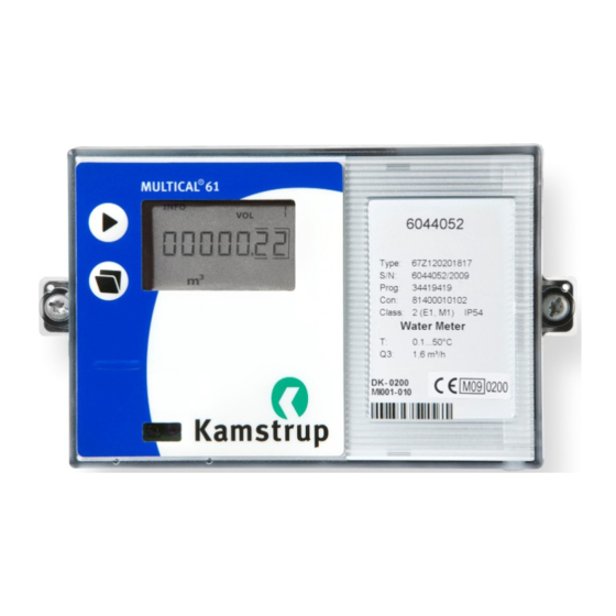
® TECHNICAL DESCRIPTION MULTICAL 1 General Description ® MULTICAL 61 is a cold water meter (0,1…50°C) and hot water meter (0,1°C…90°C) and consists of the flow sensor ® ® ULTRAFLOW 24 and the calculator MULTICAL 601. Calculator MC 601 Flow sensor UF 24 MULTICAL ®... -
Page 6: Mechanical Construction
® TECHNICAL DESCRIPTION MULTICAL 1.1 Mechanical construction Figure 1 Transparent top cover with front plate Cabinet for electronics unit Verification cover. The top cover can be dismounted without breaking the verification seal Verification label Meter case Signal case Fitting, also for wall mounting. Screws and rawlplugs for wall mounting are enclosed with the meter (item no. -
Page 7: Technical Data
® TECHNICAL DESCRIPTION MULTICAL 2 Technical Data 2.1 Approved meter data Approval DK-0200-MI001-010 EU directives MID (Measuring Instrument Directive 2004/22/EC, MI-001) LVD (Low Voltage Directive 2006/95/EC) EMC (Electromagnetic Compatibility Directive 2004/108/EC) PED (Pressure Equipment Directive 97/23/EC), Category 1,(DN50-DN80) Standard OIML R 49-1(2006), OIML R 49-2(2006) WELMEC guide 8.11 (Issue 1, 2006) Mechanical environmental class M1 Electromagnetic class... -
Page 8: Electrical Data
® TECHNICAL DESCRIPTION MULTICAL 2.2 Electrical data Supply voltage 3.6 V ± 5% Battery 3.65 VDC, D-cell lithium Replacement interval 12 years @ t < 30°C Mains supply 230 VAC +15/-30%, 50/60 Hz 24 VAC ±50%, 50/60 Hz Power consumption mains <... -
Page 9: Accuracy
® TECHNICAL DESCRIPTION MULTICAL 2.4 Accuracy MPE according to OIML R 49 MPE (maximum permissible error range) Meter approved 0.1…30°C ± 5 % in range Q ≤ Q < Q , ± 2 % in range Q ≤ Q ≤ Q 30…90°C ±... -
Page 10: Type Overview
® TECHNICAL DESCRIPTION MULTICAL 3 Type Overview 3.1 Type number, calculator ® MULTICAL 67 - Top module No module RTC (Real Time Clock) RTC + data output + hourly data logger RTC + M-Bus RTC + 2 pulse outputs for CE and CV + hourly data logger RTC + 2 pulse outputs for CE and CV + prog. -
Page 11: Type Number, Flow Sensor
® TECHNICAL DESCRIPTION MULTICAL 3.2 Type number, flow sensor Min. ® ULTRAFLOW Nom. Max. Min. Pressure Connection Length Anti- Strainer cut off flow flow flow loss on meter pollution check ∆p @ Q valve Type number [l/h] [l/h] [bar] [mm] 65-2 -CDAA -XXX... -
Page 12: Accessories
® TECHNICAL DESCRIPTION MULTICAL 3.3 Accessories 3.3.1 Glands incl. gaskets 6561-326 Gland incl. gasket for DN15, (R½ x G¾) (2 pcs.) 6561-327 Gland incl. gasket for DN20, (R¾ x G1), (2 pcs.) 6561-328 Gland incl. gasket for DN25, (R1 x G5/4) (1 pc.) 6561-329 Gland incl. -
Page 13: Programming
® TECHNICAL DESCRIPTION MULTICAL 4 Programming ® MULTICAL 61 can be ordered in countless combinations as required by the customer. First select the required hardware from the type overview. Then select ”Prog”, ”Config” and ”Data” to suit the application in question. The “Prog”... -
Page 14: Config ( Ddd-Ee-Ff-Gg-Mn )
DDD = 714 is the ”standard code” for hot water meter type 67-Z-xxxx017xx, whereas DDD = 814 is the ”standard code” for cold water meter type 67-Z-xxxx018xx. Contact Kamstrup for other combinations. A data reading can include up to 36 pieces of monthly data and up to 15 pieces of yearly data; the number is determined by the DDD-code. - Page 15 ® TECHNICAL DESCRIPTION MULTICAL 4.2.2 >EE< Configuration The EE-code is not used for MULTICAL ® 61 in connection with ULTRAFLOW ® 24 and is always “00” 4.2.3 >FF< Input A (VA), pulse division >GG< Input B (VB), pulse division MULTICAL ®...
-
Page 16: Data For Configuration
® TECHNICAL DESCRIPTION MULTICAL 4.2.4 >MN< Configuration of leak limits When MULTICAL ® 61 is used for leak surveillance, the sensitivity is determined by the configuration of ”MN”. See paragraph 8.6 Leak surveillance (V1) Leakage sensitivity (at 0.01 m resolution in display) 20 l/h (30 min. -
Page 17: Dimensioned Sketches
® TECHNICAL DESCRIPTION MULTICAL 5 Dimensioned Sketches ® MULTICAL Figure 2 Physical measurements of the electronics unit ® ULTRAFLOW 24, G¾B and G1B Figure 3 Flow sensor with G¾B and G1B threaded connection Thread ISO 228-1 Approx. weight Thread [ [ [ [ m³/h] ] ] ] [ [ [ [ mm] ] ] ] [ [ [ [ mm] ] ] ] [ [ [ [ mm] ] ] ]... - Page 18 ® TECHNICAL DESCRIPTION MULTICAL ® ULTRAFLOW 24, G1¼B and G2B Figure 4 Flow sensor with G1¼B and G2B threaded connection Thread ISO 228-1 Approx. Thread weight [ [ [ [ m³/h] ] ] ] [ [ [ [ mm] ] ] ] [ [ [ [ mm] ] ] ] [ [ [ [ mm] ] ] ] [ [ [ [ mm] ] ] ]...
- Page 19 ® TECHNICAL DESCRIPTION MULTICAL ® ULTRAFLOW 24, DN65 and DN80 Figure 6 Flow sensor with DN65 and DN80 flange connection Flange EN 1092-3, PN25 Approx. Number Nom. Bolts weight [ [ [ [ m³/h] ] ] ] diameter [ [ [ [ mm] ] ] ] [ [ [ [ mm] ] ] ] [ [ [ [ mm] ] ] ] [ [ [ [ mm] ] ] ] [ [ [ [ mm] ] ] ] [ [ [ [ mm] ] ] ] [ [ [ [ mm] ] ] ] [ [ [ [ units] ] ] ] Thread [ [ [ [ mm] ] ] ] [ [ [ [ kg] ] ] ]...
-
Page 20: Pressure Loss
® TECHNICAL DESCRIPTION MULTICAL 6 Pressure Loss According to OIML R 49 the maximum pressure loss must not exceed 0.63 bar in range Q up to and incl. Q max. 1.0 bar at Q respectively. The pressure loss is without anti-pollution check valve. The pressure loss in a sensor increases with the square of the flow and can be stated as: ×... -
Page 21: Installation
® TECHNICAL DESCRIPTION MULTICAL 7 Installation 7.1 Installation requirements ® Prior to installing the flow sensor ULTRAFLOW 24 the installation ought to be flushed while a fitting piece is replacing the meter. Remove the adhesive wafers from the meter’s inlet and outlet and mount the flow sensor with glands. -
Page 22: Installation Angle For Ultraflow ® 24
® TECHNICAL DESCRIPTION MULTICAL ® 7.2 Installation angle for ULTRAFLOW ULTRAFLOW ® 24 can be mounted vertically, horizontally or at an angle. Figure 7 Important! ULTRAFLOW ® 24 may be turned upwards to max. 45° and downwards to max. 90° in relation to the pipe axis. Figure 8 The plastic housing must not face upwards. -
Page 23: Straight Inlet
® TECHNICAL DESCRIPTION MULTICAL 7.3 Straight inlet ® ULTRAFLOW requires neither straight inlet nor outlet to meet the Measuring Instruments Directive (MID) 2004/22/EC and OIML R 49. Only in case of heavy flow disturbances before the meter a straight inlet section is necessary. -
Page 24: The Calculator
® TECHNICAL DESCRIPTION MULTICAL 8 The Calculator 8.1 Flow measurement and calculation MULTICAL ® 61 calculates the current water flow of quick volume pulses without average determination as the number of volume pulses per 10 sec. multiplied by the scaling factor. Q = (Imp./10 s. -
Page 25: Min. And Max. Flow, V1
® TECHNICAL DESCRIPTION MULTICAL 8.2 Min. and max. flow, V1 MULTICAL ® 61 can register both minimum and maximum flow on monthly as well as yearly basis. The complete registration can be read via data communication. Furthermore, a few monthly and yearly registers can be read from the display, depending on the selected DDD-code. -
Page 26: Display Functions
® TECHNICAL DESCRIPTION MULTICAL 8.3 Display functions MULTICAL ® 61 is fitted with an easily readable LCD-display including 8 digits, measuring units and information field. Volume readings use 7 digits and the corresponding measuring units, whereas 8 digits are used for display of e.g. - Page 27 ® TECHNICAL DESCRIPTION MULTICAL 8.3.1 Primary and secondary readings The top pushbutton is used to change between readings of the primary register. Consumers normally use the first primary reading in connection with self-reading for billing purposes. The lower pushbutton is used to display readings of the secondary register with additional information on the selected primary reading.
- Page 28 ® TECHNICAL DESCRIPTION MULTICAL 8.3.2 Display structure The below-mentioned diagram shows the display structure of DDD=814 with 5 primary readings and a number of secondary readings under most primary readings. The number of secondary readings in connection with yearly and monthly data has been determined under the DDD-code.
-
Page 29: Information Codes "Info
® TECHNICAL DESCRIPTION MULTICAL 8.4 Information Codes ”Info” MULTICAL ® 61 constantly monitors a number of important functions. If there is a serious error in measuring system or installation, a flashing “info” will appear in the display. The ”Info” field will flash as long as the error exists no matter which reading you choose. -
Page 30: Data Loggers
® TECHNICAL DESCRIPTION MULTICAL 8.5 Data loggers MULTICAL ® 61 includes a permanent memory (EEPROM), in which the values of various data loggers are saved. The meter includes the following data loggers: Data logging interval Data logging depth Logged value Yearly logger 15 years Counter register... -
Page 31: Leak Surveillance
® TECHNICAL DESCRIPTION MULTICAL 8.6 Leak surveillance Water installation ® MULTICAL 61 can monitor the water consumption. Possible running cisterns, leaky heating spirals of tap water tanks or other leakages will result in water flow being registered from the water meter 24 hours a day. The calculator of MULTICAL ®... -
Page 32: Reset Function
® TECHNICAL DESCRIPTION MULTICAL 8.7 Reset Function Resetting the hour counter The operating hour counter can be reset in connection with e.g. replacement of battery. As the hour counter is often used to check whether the meter has been in operation during the whole billing period (e.g. 1 year = 8760 hours) the utility or waterworks must always be informed, in which meters the hour counter has been reset. -
Page 33: The Flow Sensor
Flow sensor manufacturers have been working on alternative techniques to replace the mechanical principle. Research and development at Kamstrup has proven that ultrasonic measuring is the most viable solution. Combined with microprocessor technology and piezo ceramics, ultrasonic measuring is not only accurate but also reliable. - Page 34 ® TECHNICAL DESCRIPTION MULTICAL In principle, flow is determined by measuring the flow velocity and multiplying it by the area of the measuring pipe: × where: is the flow is the flow velocity Is the area of the measuring pipe The area and the length which the signal travels in the sensor are well-known factors.
-
Page 35: Signal Paths
® TECHNICAL DESCRIPTION MULTICAL 9.4 Signal paths Figure 16 : 1.6 m³ h : 2.5…40 m³/h 2 parallel tracks Triangle The sound path is parallel The sound path covers the with the measuring pipe and measuring pipe in a triangle is sent from the transducers and is sent from the via reflectors. - Page 36 ® TECHNICAL DESCRIPTION MULTICAL Function In the meter’s working range from min. cut off to saturation flow there is a linear connection between the flow rate and the number of pulses being emitted. The below diagram shows an example of the connection between flow ®...
-
Page 37: Flow Limits
® TECHNICAL DESCRIPTION MULTICAL 9.5 Flow limits In the meter’s working range from min. cut-off and far beyond Q there is a linear connection between the flow rate and the measured water flow. In practice the highest possible water flow through the sensor will be limited by the pressure in the system or cavitation due to too low back pressure. -
Page 38: Pulse Transmitter (Cable Extension Set) 66-99-618
® TECHNICAL DESCRIPTION MULTICAL 9.7 Pulse Transmitter (Cable extension set) 66-99-618 The pulse transmitter is used in connection with reading at large distances (up to 10 metres). Installation instructions: 5512-587 9.8 Pulse inputs VA and VB ® ® In addition to pulse input V1, to which ULTRAFLOW 24 is connected, MULTICAL 61 has two extra pulse inputs, VA and VB, for collection and remote accumulation of pulses from e.g. - Page 39 ® TECHNICAL DESCRIPTION MULTICAL The two pulse inputs are identically constructed and can be individually set up to receive pulses from water meters of max. 1 Hz, or pulses from electricity meters of max. 3 Hz. Correct pulse value is configured from the factory on the basis of order information, or by means of METERTOOL. See paragraph 4.2.3 concerning configuration of VA (FF-codes) and VB (GG-codes).
-
Page 40: Power Supply
® When supplied by a battery MULTICAL 61 uses a lithium D-cell (Kamstrup type 66-00-200-100). The battery is mounted in the right side of the connection base with the red wire connected to terminal 60(+) and the black wire to terminal 61(-). The battery is easily replaced using a screwdriver. -
Page 41: Supply Module 230 Vac
® TECHNICAL DESCRIPTION MULTICAL 10.2 Supply Module 230 VAC This PCB module is galvanically separated from the mains voltage and is suitable for direct 230 V mains installation. The module includes a double-chamber safety transformer, which fulfils the double-isolation requirements when the calculator top is mounted. The power consumption is less than 1 VA/1 W. National regulations for electric installations must be observed. -
Page 42: Change Of Supply Unit
® TECHNICAL DESCRIPTION MULTICAL The module is specially suited for installation together with a 230/24 V safety transformer, e.g. type 66-99-403, which can be installed in the meter panel before the safety relay. When the transformer is used the power consumption of the total meter incl. -
Page 43: Mains Cables
® TECHNICAL DESCRIPTION MULTICAL 10.5 Mains cables ® MULTICAL 61 is available with mains cables H05 VV-F for either 24 V or 230 V (l=1.5 m): Figure 17 Mains cable, type 5000-286 (2x0.75 mm²), max. 6 A fuse ”H05 VV-F” is the designation of a strong PVC mantle, which withstands max. 70 ° C. Therefore, the mains cable must be installed with sufficient distance to hot pipes etc. -
Page 44: Plug-In Modules
® TECHNICAL DESCRIPTION MULTICAL 11 Plug-in Modules ® MULTICAL 61 can be fitted with plug-in modules in both calculator top (top modules) and connection base (base modules) which adapt the meter to various applications. ® ® In reading systems like MULTITERM Pro and PcBase, MULTICAL 61 will appear as MULTICAL 601. - Page 45 ® TECHNICAL DESCRIPTION MULTICAL 11.1.1 Overview of top modules Type 67-01: RTC, Real Time Clock The top module consists of real time clock and battery ® backup. When the MULTICAL 61 calculator top is placed in the connection bracket, thereby being powered, the top module transfers current date and time to the calculator.
- Page 46 The RTC and pulse output functions of this top module are identical with the functions described for top module 67-08. The top module is prepared for use in a Kamstrup radio network together with the Radio Router base module 6700210003xx, read data being transferred to the system software via the network unit RF Concentrator.
- Page 47 ® TECHNICAL DESCRIPTION MULTICAL 11.1.3 Supply options for top and base modules Top ⇒ ⇒ ⇒ ⇒ 67-01 67-05 67-07 67-08 67-0B RTC + Data + Hour RTC + M-Bus RTC + pulse output RTC + pulse output Base ⇓ ⇓ ⇓ ⇓ +prog.hour log.
-
Page 48: Base Modules
Kamstrup’s hand-held terminal or hardwiring of PC connection. The data connection is galvanically isolated with optocouplers, which makes it necessary to use data cable type 6699-105 or 6699-106 in order to adapt the signal to RS232 level, which suits PC and Kamstrup’s hand-held terminal. -
Page 49: M-Bus + Pulse Inputs
The radio module is prepared to form part of a Kamstrup radio network, the read data being automatically transferred to system software via the network component/network unit, RF Concentrator. -
Page 50: 0/4
® TECHNICAL DESCRIPTION MULTICAL 11.2.5 0/4…20 mA outputs (67-00-23) The module has two active analog outputs, which can be individually configured at 0…20 mA or 4…20 mA. Furthermore, the outputs can be configured for a specific measuring value as well as the required range scaling. All output values are updated every 10 seconds. - Page 51 The standard version of the radio module is for operation in licence-free frequency bands, but it is also available for other licence demanding frequencies. The radio module is prepared to form part of a Kamstrup radio network, the read data being automatically transferred to system software via the network components RF Router and RF Concentrator.
-
Page 52: Retrofitting Modules
® TECHNICAL DESCRIPTION MULTICAL 11.3 Retrofitting modules ® Both top modules and base modules for MULTICAL 61 can be supplied separately for retrofitting. The modules are configured and ready for installation from the factory. Some of the modules require individual configuration after installation which is possible by means of METERTOOL. -
Page 53: Data Communication
The KMP protocol is used in all Kamstrup consumption meters launched in 2006 and later. The protocol is used for the optical eye and via plug pins for the base module. Thus, base modules with e.g. M-bus interface use the KMP protocol internally and the M-bus protocol externally. - Page 54 ® TECHNICAL DESCRIPTION MULTICAL ® 12.1.1 MULTICAL 61 Register IDs for water meter Register Description 1003 DATE Current date (YYMMDD) Volume register V1 Input register VA Input register VB 1004 Operating hour counter INFOEVENT Info event counter 1002 CLOCK Current hour (hhmmss) INFO Info code register, current FLOW1...
-
Page 55: Multical ® 61 Communication Paths
® TECHNICAL DESCRIPTION MULTICAL ® 12.2 MULTICAL 61 Communication paths Physically the possibility of direct communication has been implemented as shown below. Data communication can be routed internally between modules and calculator via destination addresses. OPTICAL INTERFACE ® 67-0X Module MULTICAL 61 CPU 67-00-XX Module... -
Page 56: Approvals
13.1 Type approvals MULTICAL ® 61 has been MID approved on the basis of OIML R 49-1:2006 and R 49-2:2006, with FORCE Certification as notified body. Please contact Kamstrup A/S for further details on type approvals and verification. 13.2 CE-Marking MULTICAL ®... -
Page 57: Declaration Of Conformity
® TECHNICAL DESCRIPTION MULTICAL 13.4 Declaration of Conformity 5512-622 GB/01.2011/Rev. E1... -
Page 58: Troubleshooting
Repairing the meter, if needed, we recommend only to replace parts like battery and communication modules. Alternatively the whole meter ought to be replaced. Major repairs must be made by Kamstrup A/S. Before sending in the sensor for repair or check, please use the error detection table below to help you clarify the possible cause of the problem. -
Page 59: Disposal
MULTICAL 15 Disposal Kamstrup A/S holds an environmental certification according to ISO 14001, and as part of our environment policy we use materials which can be recovered environmentally correct to the greatest possible extent. Approximately 80 % (weight) of the meter is recyclable. -
Page 60: Documents
MULTICAL 16 Documents Danish English German Technical description 5512-621 5512-622 5512-623 5512-756 Data sheet 5810-642 5810-643 5810-644 5810-713 Installation and user's guide 5512-676 5512-697 5512-700 5512-793 Terms and expressions used in this document are explained at www.kamstrup.dk 5512-622 GB/01.2011/Rev. E1...
Need help?
Do you have a question about the MULTICAL 61 and is the answer not in the manual?
Questions and answers