Kamstrup MULTICAL 62 Technical Description
Hide thumbs
Also See for MULTICAL 62:
- Installation and user manual (20 pages) ,
- Technical description (100 pages)

Subscribe to Our Youtube Channel
Related Manuals for Kamstrup MULTICAL 62


Summary of Contents for Kamstrup MULTICAL 62
- Page 1 Technical Description ® MULTICAL Water Meter Kamstrup A/S Industrivej 28, Stilling DK-8660 Skanderborg TEL: +45 89 93 10 00 FAX: +45 89 93 10 01 info@kamstrup.com www.kamstrup.com...
- Page 2 ® TECHNICAL DESCRIPTION MULTICAL 5512-1036 GB/07.2012/Rev.B1...
-
Page 3: Table Of Contents
® TECHNICAL DESCRIPTION MULTICAL Contents General Description ......................6 Mechanical construction ......................... 7 Technical Data ........................8 Approved meter data ..........................8 Electrical data ............................8 Mechanical data............................ 10 ... - Page 4 ® TECHNICAL DESCRIPTION MULTICAL The Flow Sensor ......................41 Ultrasound combined with piezo ceramics .................... 41 Principles ............................. 41 Transient time method .......................... 41 Signal paths ............................43 ...
- Page 5 ® TECHNICAL DESCRIPTION MULTICAL Troubleshooting ......................84 Disposal ........................85 Documents ........................87 5512-1036 GB/07.2012/Rev.B1...
-
Page 6: General Description
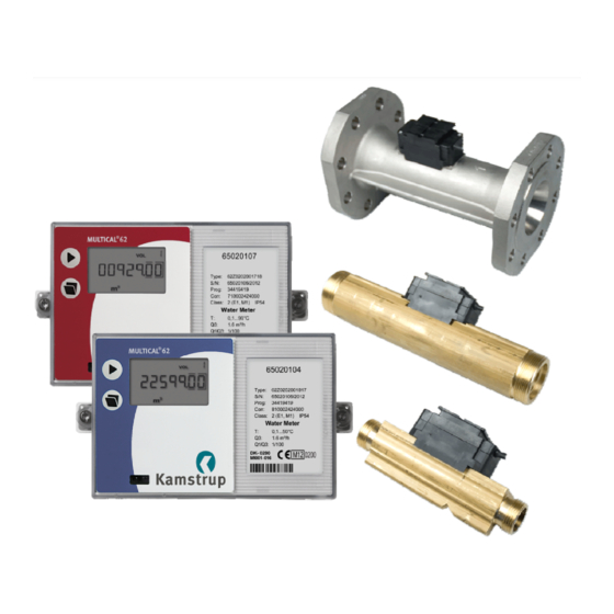
® TECHNICAL DESCRIPTION MULTICAL 1 General Description 62 is a cold water meter (0,1…50 C) and hot water meter (0,1 C…90 C) and consists of the flow ® MULTICAL ® ® sensor ULTRAFLOW 24 and the calculator MULTICAL 602. -
Page 7: Mechanical Construction
® TECHNICAL DESCRIPTION MULTICAL 1.1 Mechanical construction Figure 1 Transparent top cover with front plate (Blue cold water meter, Red hot water meter) Cabinet for electronics unit Verification cover. The top cover can be dismounted without breaking the verification seal Verification label Meter case Signal case... -
Page 8: Technical Data
® TECHNICAL DESCRIPTION MULTICAL 2 Technical Data 2.1 Approved meter data Approval DK-0200-MI001-016 EU directives MID (Measuring Instrument Directive 2004/22/EC, MI-001) LVD (Low Voltage Directive 2006/95/EC) EMC (Electromagnetic Compatibility Directive 2004/108/EC) PED (Pressure Equipment Directive 97/23/EC), Category 1,(DN50-DN80) Standard OIML R 49-1(2006), OIML R 49-2(2006) WELMEC guide 8.11 (Issue 1, 2006) Mechanical environmental class M1 Electromagnetic class... - Page 9 ® TECHNICAL DESCRIPTION MULTICAL Pulse inputs without bounce damping: Pulse inputs VA and VB Water meter connection Electricity meter connection FF(VA) and GG(VB) = 71…90 FF(VA) and GG(VB) = 50…60 VA: 65-66 and VB: 67-68 Pulse input 680 k pull-up for 3.6 V 680 k...
-
Page 10: Mechanical Data
® TECHNICAL DESCRIPTION MULTICAL 2.3 Mechanical data Metrological class Environmental class Fulfils OIML R 49 class B Mechanical environment MID class M1 Ambient temperature 5…55°C non-condensing, closed location (installation indoors) Protection class Calculator: IP54 Flow sensor: IP65 Temperature of medium Cold water meter: 0.1…30°C (T30) Cold water meter: 0.1…50°C (T50) Hot water meter: 0.1…90°C (T90) -
Page 11: Accuracy
® TECHNICAL DESCRIPTION MULTICAL 2.4 Accuracy MPE according to OIML R 49 MPE (maximum permissible error range) 5 % in range Q Q < Q , 2 % in range Q Q Q Meter approved: 0.1…30°C ... -
Page 12: Type Overview
® TECHNICAL DESCRIPTION MULTICAL 3 Type Overview 3.1 Type number, calculator ® MULTICAL 62 - Top module No module RTC + data output + hourly data logger RTC + M-Bus RTC + 2 pulse outputs for CE and CV + prog. data logger 2 Pulse outputs CE and CV Base module No module... -
Page 13: Type Number, Flow Sensor
Infrared optical reading head w/D-sub 9F 66-99-106 Data cable RS 232, D-sub 9F 66-99-397/-398/-399 Verification unit (used with METERTOOL) 679xxxxxx2xx External Communication Box ® 66-99-718 METERTOOL for MULTICAL ® 66-99-719 METERTOOL LogView for MULTICAL Please contact Kamstrup A/S for questions concerning further accessories. 5512-1036 GB/07.2012/Rev.B1... - Page 14 ® TECHNICAL DESCRIPTION MULTICAL 3.3.2 Glands incl. gaskets 6561-326 Gland incl. gasket for DN15, (R½ x G¾) (2 pcs.) 6561-327 Gland incl. gasket for DN20, (R¾ x G1), (2 pcs.) 6561-328 Gland incl. gasket for DN25, (R1 x G5/4) (1 pc.) 6561-329 Gland incl.
-
Page 15: Programming
® TECHNICAL DESCRIPTION MULTICAL 4 Programming ® MULTICAL 62 can be ordered in countless combinations as required by the customer. First select the required hardware from the type overview. Then select ”Prog”, ”Config” and ”Data” to suit the application in question. The “Prog”... -
Page 16: Config ( Ddd-Ee-Ff-Gg-Mn )
® TECHNICAL DESCRIPTION MULTICAL 4.2 CONFIG ( DDD-EE-FF-GG-MN ) 4.2.1 >DDD< CONFIGURATION OF DISPLAY Display code ”DDD” indicates the active readings of each meter type. ”1” is the first primary reading, whereas e.g. ”1A” is the first secondary reading. The display automatically returns to reading ”1” after 4 minutes. Volume Volume Volume... -
Page 17: Real Time Clock (Rtc)
DDD = 714 is the ”standard code” for hot water meter type 62-Z-xxxx0017xx, whereas DDD = 814 is the ”standard code” for cold water meter type 62-Z-xxxx0018xx. Contact Kamstrup for other combinations. A data reading can include up to 36 pieces of monthly data and up to 15 pieces of yearly data; the number is determined by the DDD-code. - Page 18 ® TECHNICAL DESCRIPTION MULTICAL 4.3.1 >EE< Configuration ® ® The EE-code is not used for MULTICAL 62 in connection with ULTRAFLOW 24 and is always “00” 4.3.2 >FF< Input A (VA), pulse division >GG< Input B (VB), pulse division ® MULTICAL 62 has two extra optional pulse inputs, VA and VB, which are placed on the base modules (see paragraph 9.8 for further details).
-
Page 19: T< Configuration Of Encryption Level
The encryption key is forwarded to the customer and ”matched” with the individual meter’s serial number in the reading system. If the encryption key is lost, the meter cannot be read. A new encryption key must be supplied by Kamstrup. Only encrypted data via the base modules can be read by Wireless M-Bus. -
Page 20: Data For Configuration
® TECHNICAL DESCRIPTION MULTICAL 4.5 DATA for configuration Automatic To be stated when ordering Default Serial no. (S/N) as well as E.g. 65000000/2012 Customer No. Up to 16 digits Customer number = S/N Display No. 1 = 8 digits MSD Limited to 11 digits depend- ing on PcBase compatibility Display No. -
Page 21: Set-Up Via The Front Keys
® TECHNICAL DESCRIPTION MULTICAL 4.6 Set-up via the front keys ® Via the main key and the sub-key on MULTICAL 62, a number of settings can be selected. 4.6.1 Activate the setup-menu The setup-menu is activated in the following way: 1) Select the display reading that you wish to change 2) Remove the calculator from the base 3) Wait until the display goes blank (up to 2.5 minutes). - Page 22 ® TECHNICAL DESCRIPTION MULTICAL 4.6.3 Exit setup-menu When the display value has been changed as required, hold the main key for 10 seconds, until the ”OK” segment is displayed. The display reverts to legal reading. The new value is checked. If it is valid, the new value is saved. If it is invalid, the old value is kept and the “OK” segment will not be displayed within approx.
-
Page 23: Reset Via The Front Keys
® TECHNICAL DESCRIPTION MULTICAL 4.7 Reset via the front keys ® Via the the main key and the sub-key on MULTICAL 62, a number of reset functions can be made. 4.7.1 Activate the reset-menu The reset-menu is activated in the following way: 1) Select the display reading that you wish to reset 2) Remove the calculator from the base 3) Wait until the display goes blank (up to 2.5 minutes). -
Page 24: Dimensioned Sketches
® TECHNICAL DESCRIPTION MULTICAL 5 Dimensioned Sketches ® MULTICAL Figure 2 Physical measurements of the electronics unit ® ULTRAFLOW 24, G¾B and G1B Figure 3 Flow sensor with G¾B and G1B threaded connection Thread ISO 228-1 Approx. Thread weight m³/h ... - Page 25 ® TECHNICAL DESCRIPTION MULTICAL ® ULTRAFLOW 24, G1¼B and G2B Figure 4 Flow sensor with G1¼B and G2B threaded connection Thread ISO 228-1 Approx. weight Thread m³/h mm mm mm mm mm mm mm kg G1¼B Table 3 ® ULTRAFLOW 24, DN50 Figure 5 Flow sensor with DN50 flange connection Flange EN 1092, PN25...
- Page 26 ® TECHNICAL DESCRIPTION MULTICAL ® ULTRAFLOW 24, DN65 and DN80 Figure 6 Flow sensor with DN65 and DN80 flange connection Flange EN 1092, PN25 Approx. Number Nom. Bolts weight m³/h diameter mm mm mm mm mm mm mm units mm kg...
-
Page 27: Pressure Loss
® TECHNICAL DESCRIPTION MULTICAL 6 Pressure Loss According to OIML R 49 the maximum pressure loss must not exceed 0.63 bar in range Q up to and incl. Q max. 1.0 bar at Q respectively. The pressure loss is without anti-pollution check valve. The pressure loss in a sensor increases with the square of the flow and can be stated as: ... -
Page 28: Installation
® TECHNICAL DESCRIPTION MULTICAL 7 Installation 7.1 Installation requirements ® Prior to installing the flow sensor ULTRAFLOW 24 the installation ought to be flushed while a fitting piece is replacing the meter. Remove the adhesive wafers from the meter’s inlet and outlet and mount the flow sensor with glands. -
Page 29: Installation Angle For Ultraflow ® 24
® TECHNICAL DESCRIPTION MULTICAL ® 7.2 Installation angle for ULTRAFLOW ® ULTRAFLOW 24 can be mounted vertically, horizontally or at an angle. Figure 7 Important! ® ULTRAFLOW 24 may be turned upwards to max. 45° and downwards to max. 90° in relation to the pipe axis. Figure 8 The plastic housing must not face upwards. -
Page 30: Straight Inlet
® TECHNICAL DESCRIPTION MULTICAL 7.3 Straight inlet ® ULTRAFLOW requires neither straight inlet nor outlet to meet the Measuring Instruments Directive (MID) 2004/22/EC and OIML R 49. Only in case of heavy flow disturbances before the meter a straight inlet section is necessary. -
Page 31: Operating Pressure
® TECHNICAL DESCRIPTION MULTICAL 7.5 Operating pressure ® In order to prevent cavitation the operating pressure at ULTRAFLOW 24 must be min. 1.6 bar at Q and min. 2.5 ® bar at Q . ULTRAFLOW 24 must not be subjected to pressure lower than the ambient pressure (vacuum). 7.6 Mounting of Pulse Transmitter 66-99-618 See installation instructions 5512-587 DK-GB-DE 5512-1036 GB/07.2012/Rev.B1... -
Page 32: The Calculator
® TECHNICAL DESCRIPTION MULTICAL 8 The Calculator 8.1 Flow measurement and calculation ® MULTICAL 62 calculates the current water flow of quick volume pulses without average determination as the number of volume pulses per 10 sec. multiplied by the scaling factor. ... -
Page 33: Min. And Max. Flow, V1
® TECHNICAL DESCRIPTION MULTICAL 8.2 Min. and max. flow, V1 ® MULTICAL 62 can register both minimum and maximum flow on monthly as well as yearly basis. The complete registration can be read via data communication. Furthermore, a few monthly and yearly registers can be read from the display, depending on the selected DDD-code. -
Page 34: Display Functions
® TECHNICAL DESCRIPTION MULTICAL 8.3 Display functions ® MULTICAL 62 is fitted with an easily readable LCD-display including 8 digits, measuring units and information field. Volume readings use 7 digits and the corresponding measuring units, whereas 8 digits are used for display of e.g. - Page 35 ® TECHNICAL DESCRIPTION MULTICAL 8.3.1 Primary and secondary readings The top pushbutton is used to change between readings of the primary register. Consumers normally use the first primary reading in connection with self-reading for billing purposes. The lower pushbutton is used to display readings of the secondary register with additional information on the selected primary reading.
- Page 36 ® TECHNICAL DESCRIPTION MULTICAL 8.3.2 Display structure The below-mentioned diagram shows the display structure of DDD=814 with 5 primary readings and a number of secondary readings under most primary readings. The number of secondary readings in connection with yearly and monthly data has been determined under the DDD-code. If not specified when ordering the water meter,, secondary readings will consist of 2 yearly data sets and 12 monthly data sets.
-
Page 37: Information Codes "Info
® TECHNICAL DESCRIPTION MULTICAL 8.4 Information Codes ”Info” ® MULTICAL 62 constantly monitors a number of important functions. If there is a serious error in measuring system or installation, a flashing “info” will appear in the display. The ”Info” field will flash as long as the error exists no matter which reading you choose. -
Page 38: Data Loggers
® TECHNICAL DESCRIPTION MULTICAL 8.5 Data loggers ® MULTICAL 62 includes a permanent memory (EEPROM), in which the values of various data loggers are saved. The meter includes the following data loggers: Data logging interval Data logging depth Logged value Logger read-out ... -
Page 39: Leak Surveillance
® TECHNICAL DESCRIPTION MULTICAL 8.6 Leak surveillance Water installation ® MULTICAL 62 can monitor the water consumption. Possible running cisterns, leaky heating spirals of tap water tanks or other leakages will result in water flow being registered from the water meter 24 hours a day. ... -
Page 40: Reset Function
® TECHNICAL DESCRIPTION MULTICAL 8.7 Reset Function 8.7.1 Resetting the hour counter As the hour counter usually is used to control that the meter has been in operation in the entire billing period (e.g. 1 year = 8760 hours) the district heating supplier must always be informed which meters have had their hour counter reset. -
Page 41: The Flow Sensor
Flow sensor manufacturers have been working on alternative techniques to replace the mechanical principle. Research and development at Kamstrup has proven that ultrasonic measuring is the most viable solution. Combined with microprocessor technology and piezo ceramics, ultrasonic measuring is not only accurate but also reliable. - Page 42 ® TECHNICAL DESCRIPTION MULTICAL In principle, flow is determined by measuring the flow velocity and multiplying it by the area of the measuring pipe: where: is the flow is the flow velocity Is the area of the measuring pipe The area and the length which the signal travels in the sensor are well-known factors.
-
Page 43: Signal Paths
® TECHNICAL DESCRIPTION MULTICAL 9.4 Signal paths Figure 18 : 1.6 m³ h : 2.5…40 m³/h 2 parallel tracks Triangle The sound path is parallel The sound path covers the with the measuring pipe and measuring pipe in a triangle is sent from the transducers and is sent from the via reflectors. - Page 44 ® TECHNICAL DESCRIPTION MULTICAL Function In the meter’s working range from min. cut off to saturation flow there is a linear connection between the flow rate and the number of pulses being emitted. The below diagram shows an example of the connection between flow ®...
-
Page 45: Flow Limits
® TECHNICAL DESCRIPTION MULTICAL 9.5 Flow limits In the meter’s working range from min. cut-off and far beyond Q there is a linear connection between the flow rate and the measured water flow. In practice the highest possible water flow through the sensor will be limited by the pressure in the system or cavitation due to too low back pressure. -
Page 46: Pulse Transmitter (Cable Extension Set) 66-99-618
® TECHNICAL DESCRIPTION MULTICAL 9.7 Pulse Transmitter (Cable extension set) 66-99-618 The pulse transmitter is used in connection with reading at large distances (up to 10 metres). Installation instructions: 5512-587 9.8 Pulse inputs VA and VB ® ® In addition to pulse input V1, to which ULTRAFLOW 24 is connected, MULTICAL 62 has two extra pulse inputs, VA and VB, for collection and remote accumulation of pulses from e.g. - Page 47 ® TECHNICAL DESCRIPTION MULTICAL The two pulse inputs are identically constructed and can be individually set up to receive pulses from water meters of max. 1 Hz, or pulses from electricity meters of max. 3 Hz. Correct pulse value is configured from the factory on the basis of order information, or by means of METERTOOL. See paragraph 4.3.2 concerning configuration of VA (FF-codes) and VB (GG-codes).
-
Page 48: Power Supply
® When power supplied by a battery MULTICAL 62 uses a lithium D-cell (Kamstrup type 66-00-200-100). The battery is mounted in the right side of the connection base with the red wire connected to terminal 60(+) and the black wire to terminal 61(-). The battery is easily replaced using a screwdriver. -
Page 49: Battery Lifetimes
® TECHNICAL DESCRIPTION MULTICAL 10.2 Battery lifetimes Supply options and battery lifetime for wall mounted MULTICAL 62 with ULTRAFLOW Estimated battery lifetime in years Top 67-00 67-05 67-07 67-0B 602-0C Without Top Data + H-Log M-Bus 2 pulse out + 2 pulse out Base ... -
Page 50: High Power Supply Module 230 Vac
® TECHNICAL DESCRIPTION MULTICAL 10.3 High Power supply module 230 VAC This PCB module is galvanically separated from the mains supply and is suited for direct 230 V mains installation. The module is a Switch Mode Power Supply (SMPS) that meets the demands for double insulation when the calculator top is mounted. -
Page 51: Supply Module 230 Vac
® TECHNICAL DESCRIPTION MULTICAL 10.5 Supply module 230 VAC This PCB module is galvanically separated from the mains supply and is suited for direct 230 V mains installation. The module contains a double chamber safety transformer that meets the demands for double insulation when the calculator top has been mounted. -
Page 52: Change Of Supply Unit
® TECHNICAL DESCRIPTION MULTICAL The module is especially suited for installation together with a 230/24 V safety transformer, e.g. type 66-99-403, that can be installed in the switch cabinet before the safety relay. When the transformer is used the power consumption will be less than 2.2 W for the entire meter including the 230/24 V transformer. -
Page 53: Mains Cables
® TECHNICAL DESCRIPTION MULTICAL 10.8 Mains cables ® MULTICAL 62 is available with mains cables H05 VV-F for either 24 V or 230 V (l=1.5 m): Figure 19 Mains cable, type 5000-286 (2x0.75 mm²), max. 6 A fuse ”H05 VV-F” is the designation of a strong PVC mantle, which withstands max. 70C. Therefore, the mains cable must be installed with sufficient distance to hot pipes etc. -
Page 54: Danish Regulations For The Connection Of Mains Operated Meters
® TECHNICAL DESCRIPTION MULTICAL 10.10 Danish regulations for the connection of mains operated meters Installation of mains connected equipment for registration of consumption (www.sik.dk, safety notification electric services no. 27/09, February 2009). The consumption of energy and resources (electricity, heat, gas and water) of the individual consumer is to an increasing extent registered by electronic meters, and often equipment for remote reading and remote control of both electronic and non-electronic meters is used. -
Page 55: Plug-In Modules
® TECHNICAL DESCRIPTION MULTICAL 11 Plug-in Modules ® MULTICAL 62 can be fitted with plug-in modules in both calculator top (top modules) and connection base (base modules) which adapt the meter to various applications. ® All plug-in modules are included in the comprehensive type test, to which MULTICAL 62 has been subjected. - Page 56 AC/DC pulses. See paragraph 2.2 Electrical data as to specifications of pulse outputs CE and CV. The top module is prepared for use in a Kamstrup radio network together with the High Power Radio Router base module 6020084, read data being transferred to the system software via network unit RF Concentrator.
- Page 57 ® TECHNICAL DESCRIPTION MULTICAL Type 602-0C: 2 pulse outputs for CE and CV This top module has two configurable pulse outputs, which are suitable for volume and energy pulses for heat meters, cooling meters and combined heat/cooling meters. The pulse resolution follows the display (fixed in the CCC- code).
- Page 58 ® TECHNICAL DESCRIPTION MULTICAL 11.1.3 Supply options for top and base modules Top 67-05 67-07 67-0B 602-0C Data + H-Log M-Bus 2 pulse out+ 2 pulse outputs Base prog.datalog (CE/CV) 67-00-10 Battery or mains Mains only Battery or mains Battery or mains Data + pulse inp.
-
Page 59: Base Modules
® TECHNICAL DESCRIPTION MULTICAL 11.2 Base modules ® The base modules for MULTICAL 62 can be divided into four groups: 67-00-1X Modules with simple functions and without a microprocessor. 67-00-2X Modules specifically developed for MULTICAL 602 and the KMP protocol. 67/602-00-3X Modules specifically developed for MULTICAL... - Page 60 Kamstrup’s hand-held terminal or hardwiring of PC connection. The data connection is galvanically isolated with optocouplers, which makes it necessary to use data cable type 6699-105 or 6699-106 in order to adapt the signal to RS232 level, which suits PC and Kamstrup’s hand-held terminal.
- Page 61 The radio module is prepared to form part of a Kamstrup radio network, the read data being automatically transferred to system software via the network component/network unit, RF Concentrator.
-
Page 62: Technical Description Multical
® TECHNICAL DESCRIPTION MULTICAL 11.2.5 0/4…20 mA outputs (67-00-23) (PCB 5550-1005) The module has two active analog outputs, which can be individually configured at 0…20 mA or 4…20 mA. Furthermore, the outputs can be configured for a specific measuring value as well as the required range scaling. All output values are updated every 10 seconds. - Page 63 The standard version of the radio module is for operation in licence-free frequency bands, but it is also available for other licence demanding frequencies. The radio module is prepared to form part of a Kamstrup radio network, the read data being automatically transferred to system software via the network components RF Router and RF Concentrator.
- Page 64 The N2 module for MULTICAL ensures simple integration from Kamstrup’s heat and cooling meters to N2 Open based systems. Adress area is 1-255 determined by the last three digits of the meters customer number.
- Page 65 ® TECHNICAL DESCRIPTION MULTICAL 11.2.13 SIOX module (Auto detect Baud rate) (602-00-64) (PCB 5920-193) SIOX is used for data reading of small and medium size groups of heat meters via cable, the data reading being presented by the main system, e.g. Mcom, Fix or Telefrang. Further information on these systems can be ordered from the supplier in question.
- Page 66 11.2.16 High Power Radio Router + 2 pulse inputs (VA, VB) (602-00-84) (PCB 5550-1116) The High Power RadioRouter module has built-in router functionality and is thus optimized to form part of a Kamstrup radio network, the read data being automatically transferred to system software via the network unit RF Concentrator.
-
Page 67: Retrofitting Modules
® TECHNICAL DESCRIPTION MULTICAL 11.3 Retrofitting modules ® Both top modules and base modules for MULTICAL 62 can be supplied separately for retrofitting. The modules are configured and ready for installation from the factory. Some of the modules require individual configuration after installation which is possible by means of METERTOOL. -
Page 68: Data Communication
The KMP protocol is used in all Kamstrup consumption meters launched in 2006 and later. The protocol is used for the optical eye and via plug pins for the base module. Thus, base modules with e.g. M-bus interface use the KMP protocol internally and the M-bus protocol externally. - Page 69 ® TECHNICAL DESCRIPTION MULTICAL ® 12.1.1 MULTICAL 62 Register IDs for water meter Register Description 1003 DATE Current date (YYMMDD) Volume register V1 Input register VA Input register VB 1004 Operating hour counter INFOEVENT Info event counter 1002 CLOCK Current hour (hhmmss) INFO Info code register, current FLOW1...
-
Page 70: Multical ® 62 Communication Paths
® TECHNICAL DESCRIPTION MULTICAL ® 12.2 MULTICAL 62 Communication paths Physically the possibility of direct communication has been implemented as shown below. Data communication can be routed internally between modules and calculator via destination addresses. OPTICAL INTERFACE ® 67/602-0X MULTICAL 62 CPU Module 67/602-00-XX Module... -
Page 71: Verification
® TECHNICAL DESCRIPTION MULTICAL 13 Verification 13.1 High resolution volume for test If high resolution volume reading (V1HighRes) is needed during test or verification of the meter, it can be initialized as follows: Lift the calculator top off the connection base and wait until the display goes blank. Activate the sub-key and place the calculator top on the connection base again, keep the key down for approx. -
Page 72: Metertool For Multical 62
Partial reconfiguration USB 3-wire type 66-99-098 Partial reconfiguration via module Using equipment with Kamstrup USB, the USB driver must be installed before connection. 14.1.3 Installation Check that system requirements are fulfilled. Close other open programs before starting the installation. Insert the CD into your drive and follow the instructions. -
Page 73: Metertool Multical ® 62
® TECHNICAL DESCRIPTION MULTICAL ® 14.2 METERTOOL MULTICAL 14.2.1 General information It is important to be familiar with the calculator’s functions before starting programming. There are two programming options ”Partial programming” and ”Total programming”. ”Partial programming” does not allow change of coding which is important to energy calculation, e.g. type number and program number. - Page 74 ® TECHNICAL DESCRIPTION MULTICAL 14.2.3 File The menu “File” includes printer setup as well as possible printout of new meter label or test certificate. Exit Close METERTOOL Certificate Initiates printout of test certificate Print Label Initiates printout of meter label Select Label Printer Printer setup 14.2.4 Utility The menu ”Utility”...
- Page 75 ® TECHNICAL DESCRIPTION MULTICAL Open ”Flowpart Communication” and activate ”Get” in order to read the meter's setup of communication with the flow sensors. Mark your required settings for flow sensor 1 and flow sensor 2. Having made your choice, activate ”Set” to send the change to the meter. The meter now supports the selected setup.
- Page 76 ® TECHNICAL DESCRIPTION MULTICAL 14.2.6 Top module The menu ”Top module” includes identification as well as configuration of the top module mounted in MULTICAL Top modules and possible configurations are described in paragraph 11.1 Top modules. 14.2.7 Base modules The menu “Base modules”...
-
Page 77: Verification With Metertool Multical 602
® TECHNICAL DESCRIPTION MULTICAL 14.3 Verification with METERTOOL MULTICAL 14.3.1 General information Verification of MULTICAL 62 requires verification equipment as well as loading of verification data into the METERTOOL program. 14.3.2 Verification equipment Verification equipment, e.g. type 66-99-399, is used for verification of calculators type MULTICAL 62. - Page 78 In order to avoid unintentional change of calibration data this writing is protected by a password, which can be obtained from Kamstrup A/S. Calibration data include test points, permissible error, uncertainty, ambient temperature (fixed value) and number of integrations per test.
- Page 79 ® TECHNICAL DESCRIPTION MULTICAL Activate ”Start verification” in order to begin test/verification. Select ”Volume only”, if relevant. If ”Energy & volume” is selected, the "Error" fields under ”Energy test results” will become red, as MULTICAL does not measure temperature and thereby not energy. When the test has been completed, the result is displayed.
-
Page 80: Logview Multical 62
® TECHNICAL DESCRIPTION MULTICAL 14.4 LogView MULTICAL 14.4.1 Introduction and installation Regarding ”Introduction”, ”Interface” and ”Installation” see paragraph 14.1 Introduction METERTOOL. LogView for MULTICAL 602 applies to MULTICAL 62 too. 14.4.2 General information ”LogView MULTICAL 602”... - Page 81 ® TECHNICAL DESCRIPTION MULTICAL 14.4.10 Application Double click on link or icon for ”LogView MULTICAL 602” in order to start the program and select the required data function. Note! Do not forget to set up the COM port the first time the program is used. ”Daily Data”...
-
Page 82: Approvals
15.1 Type approvals ® MULTICAL 62 has been MID approved on the basis of OIML R 49-1:2006 and R 49-2:2006, with FORCE Certification as notified body. Please contact Kamstrup A/S for further details on type approvals and verification. 15.2 CE-Marking ® MULTICAL... -
Page 83: Declaration Of Conformity
® TECHNICAL DESCRIPTION MULTICAL 15.4 Declaration of Conformity 5512-1036 GB/07.2012/Rev.B1... -
Page 84: Troubleshooting
Repairing the meter, if needed, we recommend only to replace parts like battery and communication modules. Alternatively the whole meter ought to be replaced. Major repairs must be made by Kamstrup A/S. Before sending in the sensor for repair or check, please use the error detection table below to help you clarify the possible cause of the problem. -
Page 85: Disposal
MULTICAL 17 Disposal Kamstrup A/S is environmentally certified according to ISO 14001, and as far as possible and as part of our environmental policy we use materials that can be recycled in an environmentally correct way. Kamstrup A/S has calculated carbon footprint of all meters. - Page 86 Gaskets EPDM Plastic recovery Packing Environmental cardboard Cardboard recycling Packing Polystyrene EPS recovery Please send any questions you may have regarding environmental matters to: Kamstrup A/S Att.: Quality and environmental department Fax.: +45 89 93 10 01 info@kamstrup.dk 5512-1036 GB/07.2012/Rev.B1...
-
Page 87: Documents
TECHNICAL DESCRIPTION MULTICAL 18 Documents Danish English German Technical description 5512-1035 5512-1036 5512-1037 5512-1038 Data sheet 5810-1034 5810-1035 5810-1036 5810-1038 Installation and user's guide 5512-1070 5512-1068 5512-1069 5512-1100 Terms and expressions used in this document are explained at www.kamstrup.dk 5512-1036 GB/07.2012/Rev.B1... - Page 88 ® TECHNICAL DESCRIPTION MULTICAL 5512-1036 GB/07.2012/Rev.B1...
Need help?
Do you have a question about the MULTICAL 62 and is the answer not in the manual?
Questions and answers