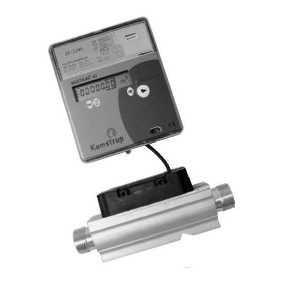
Kamstrup MULTICAL 41 Installation And User Manual
Hide thumbs
Also See for MULTICAL 41:
- Installation manual (13 pages) ,
- Technical description (44 pages)
Table of Contents
Advertisement
Quick Links
Advertisement
Table of Contents

Summary of Contents for Kamstrup MULTICAL 41
- Page 1 Installation and User’s Guide MULTICAL® 41 Water Meter www.kamstrup.com...
- Page 3 MULTICAL® 41 English Kamstrup A/S Industrivej 28, Stilling, DK-8660 Skanderborg TEL: +45 89 93 10 00 · FAX: +45 89 93 10 01 info@kamstrup.com · www.kamstrup.com...
-
Page 4: General Information
1. General information Please read these instructions before installing the heat meter. Kamstrup’s guarantee obligations do not apply in case of incorrect installation. Please note the following installation requirements: Max. inlet pressure for meters with screw-joints is 16 bar. 1.1 MID designations The meter is approved according to MID (OIML R49). - Page 5 Type label Current flow per duration LCD display Accumulated flow since latest Pushbutton reset Optical interface Number of operating hours 2. Information codes “E” MULTICAL® 41 constantly monitors a number of important functions. If a serious error occurs in the metering system or in the installation, an “E”...
- Page 6 3. Mounting Before mounting the flow part (flow sensor), flush the system thoroughly and remove protection plugs/plastic membranes from the flow sensor. The flow direction is indicated by an arrow on the side of the flow sensor. To prevent cavitation the operating pressure at the flow sensor must be min.
-
Page 7: Straight Inlet
3.1 Straight inlet MULTICAL® 41 requires neither straight inlet nor outlet to meet the Measuring Instruments Directive (MID) 2004/22/EC and OIML R 49. Only in case of heavy flow disturbances before the meter will a straight inlet section be necessary. 3.2 Installation angle The flow sensor can be mounted vertically,... -
Page 8: Mounting The Calculator
3.3 Mounting the calculator 41 mm 90 mm 27 mm MULTICAL® 41 mounted on ULTRAFLOW®, by means of angle fitting 3026-252. Wall mounting of MULTICAL® 41. -
Page 9: Power Supply
The battery cannot be and must neither be charged nor hortcircuited. Used batteries must be handed in for approved destruction e.g. at Kamstrup A/S. 4.2 Mains modules The modules are in protection class II and are connected via a two-wire cable (without earth) through the cable bush of the calculator placed at the top left corner of the connection unit. - Page 10 24 VAC Black Use a transformer, e.g. type 66-99-403 for a 24 VAC supply module. NB! This module cannot be supplied from 24 VDC. 230 VAC Black This module is used for direct mains connection.
-
Page 11: Operational Check
5. Operational check Carry out an operational check when the water meter is completely mounted. Activate the push-button on MULTICAL® 41 and check that reliable display values for water flow etc. appears. 6. Electrical connection Terminal no. Connection Supply (red) Supply (black) -
Page 12: Plug-In Modules
7. Plug-in modules MULTICAL® 41 can be retrofitted with a number of extra functions by means of plug-in modules. Below is a brief description of the individual modules. 7.1 Data/pulse inputs 65 - 66 Input A f < 0.5 Hz The data terminals are e.g. - Page 13 7.2 M-Bus/pulse inputs The M-Bus module can be mounted in star, ring or bus topology. The M-Bus module is available in two versions: • supporting primary addressing • supporting primary and secondary addressing The M-Bus network is connected to the terminals 24 and 25.
-
Page 14: Radio/Pulse Inputs
7.3 Radio/pulse inputs The radio module is used for wireless reading of MULTICAL® 41. When connecting the supply voltage the radio module retrieves the type and meter number of the meter and transfers data to the memory of the module. The radio module is ready to communicate in less than 10 seconds. - Page 15 Primary register: Secondary readings: Water consumption Totalized water consumption on input A NB! The view only occurs if the system has several inputs Number of operating Totalized water hours consumption on input B NB! The view only occurs if the system has several inputs ...
-
Page 16: Volume Measuring
Q4: 2,0 m Q2: 0,026 m Q3/Q1: 1/100 Please contact the water supplier if you require further details. Please note! The arrow indicates the type of reading. To the right on the display the measuring unit is displayed. www.kamstrup.com...


Need help?
Do you have a question about the MULTICAL 41 and is the answer not in the manual?
Questions and answers