Silicon Laboratories Si4700 User Manual
Hide thumbs
Also See for Si4700:
- User manual (164 pages) ,
- User manual (116 pages) ,
- Programming manual (256 pages)
Advertisement
Quick Links
Si4700/01 E
1. Introduction—Si4700/01 EVB
Thank you for purchasing the Silicon Laboratories, Inc. Si4700/01 FM Tuner Evaluation Board (EVB). This EVB
and associated software has been designed to speed the overall development process and decrease the required
development time from EVB to product launch. We are looking forward to working with you, and have posted
support articles, answers to frequently asked questions, and application notes at https://www.mysilabs.com.
The Si4700/01 EVB kit should include the following important items:
Si4700/01 FM Tuner customer welcome and evaluation letter
Si4700/01 Errata
Si4700/01 base board Revision 1.1 (blue)
Si4700/01 daughter card with Si470x pre-mounted Revision 1.0 (red)
Wall transformer certified at 5 V/2 A, 100–240 V ac input with two jumpers (black) and
power input terminal (green)
USB cable
BNC to RCA adapters
RCA cable
Barrel adapter (1) mini jack
EVB Characterization report for included EVB
Si4700/01 Quick Start Guide
Si4700/01 CD including:
Data sheet
Development application GUI
Firmware (embedded in Development GUI)
2. Overview
The Si4700/01 Evaluation Kit includes an evaluation board (EVB) to facilitate evaluation of the Si4700/01 using the
associated software. The EVB consists of a base board (blue) with a pre-mounted daughter card (red) - the
Si4700/01 is pre-installed on the daughter card. Several input/output (I/O) connections provide access to the
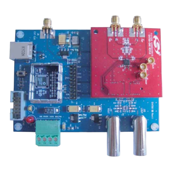
various subsystems on the EVB. Refer to Figure 1 for the locations of the various I/O connectors/devices.
3. Description
The following sections refer to both the image in Figure 1 and the silk screen on the Si4700/01 EVB. It is
recommended to refer to both when using this guide.
Rev. 0.2 5/05
Silicon Laboratories Confidential. Information contained herein is covered under non-disclosure agreement (NDA).
B
V A L U A T I O N
Copyright © 2005 by Silicon Laboratories
U
'
O A R D
S E R
S
AN232
G
U I D E
AN232
Advertisement

Related Manuals for Silicon Laboratories Si4700


Summary of Contents for Silicon Laboratories Si4700
- Page 1 EVB. Refer to Figure 1 for the locations of the various I/O connectors/devices. 3. Description The following sections refer to both the image in Figure 1 and the silk screen on the Si4700/01 EVB. It is recommended to refer to both when using this guide.
- Page 2 AN232 Figure 1. Locations of I/O Connectors/Devices The base board has the following I/O connectors/devices: USB connector for USB interface JTAG connector for the C8051F320 MCU 20-pin Expansion I/O connector Power input terminal block Daughter card connector (not visible when the base board and daughter card are mated) SMA connector for external clock input BNC connector for left audio output BNC connector for right audio output...
- Page 3 3.1.2. Reference Clock for the Si4700/01 The Si4700/01 accepts a 32.768 kHz reference clock input at the RCLK pin. On the EVB, this clock is provided by a precision crystal oscillator. The output of the oscillator is routed to the Si4700/01 RCLK pin through a Schmitt- trigger buffer (U5) and a 33 Ω...
- Page 4 The EVB includes a high-output drive dual op-amp chip (U2) to buffer the audio outputs at the LOUT and ROUT pins of the Si4700/01. U2 is located on the bottom layer of the daughter card and is not visible when the base board and daughter card are mated.
- Page 5 AN232 4. EVB Configuration Matrix Table 1 lists the configuration options the EVB provides, the hardware changes necessary to implement a certain option, and any associated constraints. Figure 2 shows the locations of the various components required to configure the EVB. Figure 2.
- Page 6 AN232 Table 1. EVB Configuration Matrix Configuration Value of Configuration Hardware Changes Constraints Variable Variable Reference clock Crystal oscillator on EVB None (default option). None source Reference clock External clock Depopulate R19. Populate 32.768 kHz, CMOS switch- R20 with 0 Ω. source ing level, VIO voltage supply from an external clock...
-
Page 7: Hardware Setup
Note: The EVB kit includes a 5 V wall transformer with ends that are not stripped, two black jumpers (also not stripped), and a green power input terminal block (designated as J4 in Figure 1 of the Si4700/01 Evaluation Board User's Guide). Strip the ends of the 5 V wall transformer and connect the white wire to the input of the power input terminal block correspond- ing to the VRADIO supply ("5 V"... -
Page 8: Getting Started-Software Installation
Windows XP and Windows 2000. To get started, insert the Silicon Laboratories, Inc. Si4700/01 CD into the host machine CD drive and launch Windows Explorer. Open the CD to explore the contents in a window like the one shown in Figure 4 below. - Page 9 Figure 5. Launching Si470x FM Tuner Application The first Si4700/01 window will show the application "searching for devices…" in the "Status Window" and the EVB serial number in the "Select Device" window. Select the target device by clicking on the EVB serial number. The progress bar on the bottom of the window will show initialization progress.
- Page 10 Figure 7. Configuration Screen Successfully Initializing Device TIP 1. If the Si4700/01 Development GUI doesn't find your device, try unplugging and plugging in the USB cable again, pushing the "reset" button on the baseboard, connecting the power again, or re-launching the software.
- Page 11 AN232 7. Development Using Si4700/01 GUI 7.1. Registers Window The "Registers" window can be easily accessed by clicking the registers window shortcut shown in Figure 8. The “Registers” window provides visibility to the state of each register and associated bits of the selected chip. As developers become more familiar with the registers and their functions, they may change the registers directly in the registers window.
- Page 12 AN232 Figure 10. Radio Window Rev. 0.2...
- Page 13 The user must powerup the Si4700/01 by clicking the Powerup button (11), or reinitializing the chip through the Configuration screen. Use the Chip Reset button if system is in non-desired state. The Si4700/01 EVB also has a physical reset button.
- Page 14 AN232 Table 2. Control Bit Explanations (Continued) Number(s) Explanation(s) Busmode selects the control interface between either 2-wire or 3-wire. A chip reset occurs when changing the Busmode. Automatic Gain Control (AGC) on / off button. AGC is controlled through bit 04h;10. The default is AGC enabled and High-Z in the LNA impedance selector (14).
- Page 15 AN232 Table 2. Control Bit Explanations (Continued) Number(s) Explanation(s) GPIO1 is reserved for the purpose of firmware downloads. GPIO2 drop down sets the GPIO2 pin state. This is independent of GPIO1 and GPIO3. GPIO3 drop down sets the GPIO3 pin state. This is independent of GPIO1 and GPIO2. Update button allows developer to stop automatic bus updates of the system.
- Page 16 3. Launch the add/remove hardware wizard / application in the control panel. The wizard will search the host for newly added items. The wizard will display the Si4700/01 EVB as "USB API". 4. Select "Install the software automatically (Recommended)" as shown in Figure 11.
- Page 17 AN232 Figure 12. Windows Hardware Update Wizard This should complete the USBXpress installation of the Si4700/01 EVB. Rev. 0.2...
- Page 18 AN232 Troubleshooting To check if the driver is correctly installed, open the “System Properties” on the “Control Panel.” Go to the “Hardware” tab and click “Device Manager.” Under “Universal Serial Bus Controllers,” you should find “USBXpress” listed without any “X” or “!” marks on it. Figure 13.
-
Page 19: Document Change List
AN232 OCUMENT HANGE Revision 0.1 to Revision 0.2 Added “wall transformer” bullet in "1. Introduction—Si4700/01 EVB" on page 1. Updated Figure 3 on page 7. Added note to step 1 on page 7. Rev. 0.2... -
Page 20: Contact Information
Silicon Laboratories products are not designed, intended, or authorized for use in applications intended to support or sustain life, or for any other application in which the failure of the Silicon Laboratories product could create a situation where per- sonal injury or death may occur.
Need help?
Do you have a question about the Si4700 and is the answer not in the manual?
Questions and answers