Table of Contents
Advertisement
Quick Links
Advertisement
Table of Contents

Related Manuals for SIG MESSERSCHMITT Bf-109


Summary of Contents for SIG MESSERSCHMITT Bf-109
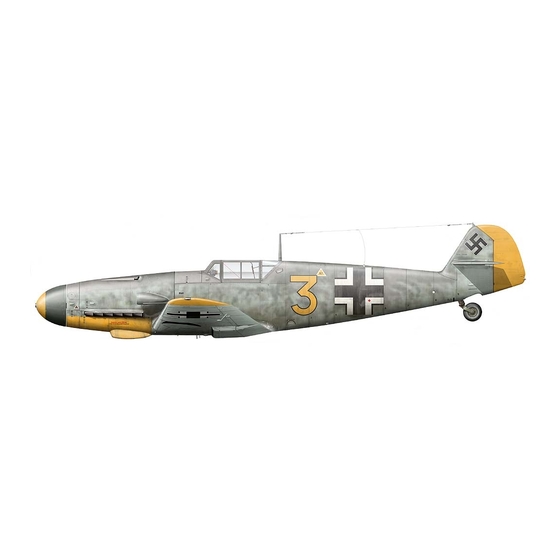
- Page 2 The SIG Messerschmitt Bf-109 ARF is a sport scale model, not necessarily based on any particular full-scale variant. covering is printed with color and markings representing typical German aircraft of the era, including details such as panel lines and national markings. The builder can add unit markings and other details of his own choice to make a convincing replica of this great German warplane.
-
Page 3: Radio Systems
• Wire cutters process are quite durable and bond to the covering film extremely • A selection of glues - thin, medium, and thick SIG CA, well. Normal handling and flying conditions should have little, if any SIG Epoxy Glue (5 and 30 minute types) and effect on the printed finish. -
Page 4: Wing Assembly
Bag #3 Full Span Wing, ailerons installed with 3 CA hinges on 2 ea. T2 x 8 mm PWA screws each but not glued, aileron servo hatches installed 2 ea. 3 mm ID x 6 mm silicone tube with 4 ea T2 x 6 mm PWA screws keepers Bag #4 Fuselage with top hatch/cockpit installed and retained... - Page 5 can be used to accurately place and center the hinge equally into create free and easy movement. We also suggest pulling on the both the wing panel and the aileron. To do this, use a business aileron at each hinge location, making sure each hinge is firmly in card and a pair of scissors to cut some "wedges".
- Page 6 hole locations onto the mounting blocks. moves through one rib and up to another. Keep doing this until the connector appears at the exit hole. Pull the connector up through Remove the servo and drill pilot holes for the servo mounting the hole and temporarily tape it to the wing surface.
-
Page 7: Main Landing Gear Installation
to its bottom surface. Repeat this process on the opposite aileron. trailing edge. These two lines are used to align the radiators. The Use the four M2 x 20 mm bolts and the two plastic control horn black painted inlet side of these covers faces forward towards the backing plate to now mount each aileron horn to the bottom of leading edge, with the front of the cover even with the rectangle each aileron with the backing plates on top of each aileron to... - Page 8 freely with just a small amount of left and right "play". Once in position, firmly tighten the setscrew in the wheel collar. Repeat this process with the remaining wheel. The wing assembly is now complete and ready to use. Set it aside for now.
-
Page 9: Rudder & Elevator Servo Installation
2) Working through the fuselage wing saddle opening, feed RUDDER & ELEVATOR SERVO INSTALLATION: the motor wires from your ESC forward into the nose, under the As mentioned earlier, the rudder and elevator servos do not need battery tray, until they exit below the motor. Plug the motor wires to be the sub-micro type used for the aileron servos. -
Page 10: Mounting The Cowl
The servos are now tested using the radio system. Connect the spinner backplate in its running position, allowing the cowl to be appropriate rudder and elevator servo leads into the receiver, turn accurately mounted to the fuselage. on the transmitter, and connect the flight battery to the ESC lead. Make sure the rudder and elevator trims are at neutral. - Page 11 We highly 6) Lightly coat the bare wood gluing surfaces on both sides of the fin with SIG Super-Weld white glue. Then, lightly coat both sides of the fin slot in the fuselage, again with white glue. Carefully slide the fin into the fuselage slot and wipe off any excess glue with a wet paper towel.
-
Page 12: Hinging The Control Surfaces
HINGING THE CONTROL SURFACES: The following steps will require the following parts: the plastic control horn backplate to secure the control horn in Rudder & elevator with CA hinges - 6 hinges total place. Cut-off the excess bolt ends and file smooth. Bag #8 - Tail Wheel assembly Bag #10 - 2 ea. - Page 13 hinges and surrounding wood. Once sufficient time has passed, move the rudder briskly left and right to free up its movement. 6) The pushrod connections are now made between the elevators and rudder and their corresponding servos. Starting with the elevator pushrod, slide a pushrod connector onto the elevator pushrod wire.
-
Page 14: Final Details
Use a fine applicator tip and thin CA to place a drop of glue into the screw holes in the fuselage to "harden" them. Reinstall the braces and screws. FINAL DETAILS: The canopy is now mounted in place over the cockpit. From the kit parts, locate the canopy and the four T2 x 6 mm PWA mounting screws. - Page 15 PREPARING THE SPINNER: 3) Use thick CA glue or 5-minute epoxy to glue the two 20 mm The plastic spinner cone supplied with this kit has a unique shape, dia. plywood washers together with their center holes aligned. peculiar to the Bf-109 and is supplied uncut. This is to allow the Glue the laminated 20 mm washer assembly to the inside flat nose builder to use it for a 2 or 3 bladed prop for either flying or display.
-
Page 16: Center Of Gravity
Modeler’s Note: A standard 2-3/4" dia. yellow nylon spinner, fly, it is, none-the-less, a warbird type aircraft and is less tolerant to such as a SIG # SIGSP2755, can be used to make a nice improper C.G. locations than other model types. - Page 17 Again, as shown, the battery pack, in place in the battery tray, now If you don't, make any adjustments needed to achieve positive sits directly behind the motor with a piece of scrap 1/4" balsa in ground control. Once you are satisfied with the taxi tests, line the place to keep it from shifting.
- Page 18 Bf-109 for a landing. use and suggest fresh, good quality paper towels and a silicone free cleaner for degreasing and polishing. SIG makes one of the We always suggest that you make your landings using a standard best cleaners for this purpose - Pure Magic Airplane Cleaner.
-
Page 19: Academy Of Model Aeronautics
SIG MANUFACTURING COMPANY, INC. is committed to your success in both assembling and flying the MESSERSCHMITT Bf-109 ARF kit. Should you encounter any problem building this kit, or discover any miss- ing or damaged parts, please feel free to contact us by mail or telephone.
Need help?
Do you have a question about the MESSERSCHMITT Bf-109 and is the answer not in the manual?
Questions and answers