
Subscribe to Our Youtube Channel
Related Manuals for Rosemount 4600


Summary of Contents for Rosemount 4600
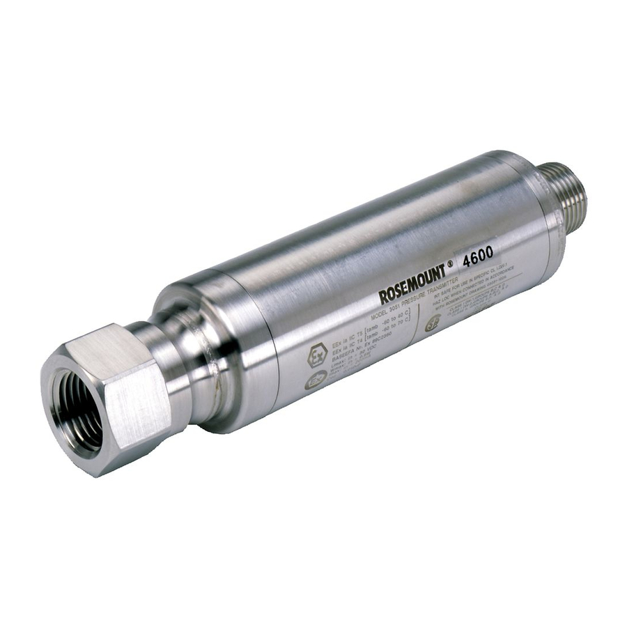
- Page 1 Reference Manual 00809-0100-4022, Rev AA July 2002 Model 4600 Oil & Gas Panel Transmitter www.rosemount.com...
- Page 3 The products described in this document are NOT designed for nuclear-qualified applications. Using non-nuclear qualified products in applications that require nuclear-qualified hardware or products may cause inaccurate readings. For information on Rosemount nuclear-qualified products, contact your local Rosemount Sales Representative. www.rosemount.com...
-
Page 5: Table Of Contents
Reference Manual 00809-0100-4022, Rev AA Model 4600 July 2002 Table of Contents SECTION 1 Using This Manual ........1-1 Introduction Service Support . - Page 6 Reference Manual 00809-0100-4022, Rev AA Model 4600 July 2002 Sensor Temperature........3-6 HART Communicator .
- Page 7 Reference Manual 00809-0100-4022, Rev AA Model 4600 July 2002 Changing a Transmitter Address ......3-22 HART Communicator ....... 3-22 AMS.
- Page 8 Reference Manual 00809-0100-4022, Rev AA Model 4600 July 2002 TOC-4...
-
Page 9: Using This Manual
July 2002 Section 1 Introduction USING THIS MANUAL The sections in this manual provides information on installing, operating, and maintaining the Rosemount Model 4600 transmitter. The sections are organized as follows: • Section 2: Installation contains mechanical and electrical installation instructions. -
Page 10: Service Support
To expedite the return process outside of the United States, contact the nearest Rosemount representative. Within the United States, call the Rosemount National Response Center using the 1-800-654-RSMT (7768) toll-free number. This center, available 24 hours a day, will assist you with any needed information or materials. -
Page 11: Overview
Reference Manual 00809-0100-4022, Rev AA Model 4600 July 2002 Section 2 Installation Safety Messages ....... . . page 2-1 General Considerations . -
Page 12: Warnings
Reference Manual 00809-0100-4022, Rev AA Model 4600 July 2002 Warnings Explosions can result in death or serious injury. • Transmitters located in hazardous areas should be installed in accordance with local codes and requirements for that area. • Verify that the operating atmosphere of the transmitter is consistent with the appropriate hazardous locations certifications. - Page 13 Reference Manual 00809-0100-4022, Rev AA Model 4600 July 2002 Figure 2-1. HART Installation Flowchart START HERE Bench Calibration? Field Install (Section 2) Mount Transmitter Configure (page 2-4) Verify (Section 3) Wire Transmitter (pages 2-6–2-9) Confirm Set Units Transmitter Configuration (page 3-5)
-
Page 14: Installation Procedures
2002 section 501:5 (A) and 501.5 (B). No additional conduit seal is required. NOTE The Model 4600 features a reliable dual process seal design which meets the © requirements of NEC 2002 section 501:5 (F)(3) and API 14F 6.8.2.2. No additional process sealing is required. -
Page 15: Impulse Piping
Reference Manual 00809-0100-4022, Rev AA Model 4600 July 2002 Impulse Piping The piping between the process and the transmitter must accurately transfer the pressure to obtain accurate measurements. There are five possible sources of error: pressure transfer, leaks, friction loss (particularly if purging is used), trapped gas in a liquid line and liquid in a gas line. -
Page 16: Connect Wiring And Power Up
(RFI). Inductive-based transient protectors with more than 3 mH of inductance can adversely affect the output of the Model 4600 transmitter. If your application requires transient protection, it is recommended that you order a transmitter with the transient protection option specified. -
Page 17: Surges/Transients
Reference Manual 00809-0100-4022, Rev AA Model 4600 July 2002 Figure 2-3. Power Supply Load Limitations, 4–20 mA Maximum field loop Resistance = 43.5 * (Power Supply Voltage - 11.25) Transmitters 1387 Operating Region 11.25 Voltage (V dc) *Communication requires a minimum loop resistance of 250 ohms. -
Page 18: Re-Zeroing
3. Verify that the output is 4mA. HAZARDOUS The Model 4600 transmitter has an explosion-proof housing. Individual transmitters are clearly marked with a tag indicating the certifications they LOCATIONS carry. See Appendix B: Approval Information for additional information. -
Page 19: Grounding The Transmitter Case
• Internal Ground Connection: The green lead provides the internal ground connection, and is standard on all Model 4600 transmitters. • External Ground Assembly: This assembly is included with the optional transient protection (Option Code T1). The External Ground Assembly can also be ordered with the transmitter (Option Code D4), or as a spare part (4600-0113-0001). - Page 20 Reference Manual 00809-0100-4022, Rev AA Model 4600 July 2002 2-10...
-
Page 21: Overview
This section contains information on commissioning and tasks that should be performed on the bench prior to installation. This section contains the Model 4600 HART configuration information. HART Communicator and AMS instructions are given to perform configuration functions. For convenience, HART Communicator fast key sequences are labeled “Fast Keys”... -
Page 22: Commissioning On The Bench With Hart
Communicator or AMS. Connect HART Communicator leads at any termination point in the signal loop. In order to commission the Model 4600, the power supply must provide 11.25 to 42.4 V dc at the transmitter terminals. A current meter is also required to measure current output. -
Page 23: Wiring Diagrams
Reference Manual 00809-0100-4022, Rev AA Model 4600 July 2002 Wiring Diagrams Bench Hook-up Connect the bench equipment as shown in Figures 3-1, and turn on the HART Communicator by pressing the ON/OFF key or log into AMS. The HART Communicator or AMS will search for a HART-compatible device and indicate when the connection is made. -
Page 24: Model 275 Hart Communicator
00809-0100-4022, Rev AA Model 4600 July 2002 MODEL 275 HART The following menu indicates fast key sequences for common functions. For full Model 275 menu tree see www.rosemount.com. COMMUNICATOR Function HART Fast Key Sequence Alarm Level Config. 1, 4, 2, 7, 7... -
Page 25: Review Configuration Data
Reference Manual 00809-0100-4022, Rev AA Model 4600 July 2002 REVIEW NOTE Information and procedures in this section that make use of HART CONFIGURATION DATA Communicator fast key sequences and AMS assume that the transmitter and Fast Keys 1, 5 communication equipment are connected, powered, and operating correctly. -
Page 26: Check Output
Scaled Variable (SV) NOTE Regardless of the range points, the Model 4600 will measure and report all readings within the digital limits of the sensor. For example, if the 4 and 20 mA points are set to 0 and 1,000 psi, and the transmitter detects a pressure of 2,500 psi, it digitally outputs the 2,500 psi reading and a 250% of span reading. -
Page 27: Basic Setup
NOTE Transmitters are shipped from Rosemount Inc. fully calibrated per request or by the factory default of full scale (span = upper range limit.) Use one of the methods below to rerange the transmitter. Each method is unique;... -
Page 28: Rerange With A Hart Communicator Only
Reference Manual 00809-0100-4022, Rev AA Model 4600 July 2002 Rerange with a HART Communicator Only Fast Keys 1, 2, 3, 1, 1 The easiest and most popular way to rerange is to use the HART Communicator only. This method changes the values of the analog 4 and 20 mA points independently without a pressure input. -
Page 29: Rerange With Ams Only
Reference Manual 00809-0100-4022, Rev AA Model 4600 July 2002 Figure 3-2. Local Zero and Span Locations Local Zero and Span Locations Magnetic Span target Magnetic Zero target Rerange with AMS only Right click on the device and select “Configuration Properties” from the menu. -
Page 30: Detailed Setup
NOTE Under some failure conditions, the transmitter will ignore user configured alarm conditions and drive the transmitter to low alarm. The Model 4600 transmitter have three configurable options for failure mode alarm and saturation levels: • Rosemount (Standard), see Table 3-1 •... -
Page 31: Alarm And Saturation Level Configuration
1. Click Next after setting the control loop to manual. 2. Click Next after acknowledging the current alarm levels. 3. Select the desired alarm settings: NAMUR, Rosemount, Other 4. If “Other” is selected, enter desired “HI Value” and “LO Value” custom values. -
Page 32: Alarm And Saturation Values For Multidrop Mode
Reference Manual 00809-0100-4022, Rev AA Model 4600 July 2002 Alarm and Saturation Transmitters set to multidrop mode handle saturation and alarm conditions differently. Values for Multidrop Mode Alarm Conditions: • Primary variable is sent with a status bit set •... -
Page 33: Ams
Reference Manual 00809-0100-4022, Rev AA Model 4600 July 2002 Right click on the device and select “Configuration Properties” from the menu 1. In the “Analog Output” tab, locate the “Configuration Pressure Alerts” box, enter “Press Hi Alert Val” and “Press Lo Alert Val” to configure the pressure alerts. -
Page 34: Hart Communicator
Reference Manual 00809-0100-4022, Rev AA Model 4600 July 2002 HART Communicator To configure the scaled variable with a HART Communicator, perform the following procedure: 1. From the HOME screen follow the fast key sequence shown. 2. Select OK after the control loop is set to manual. -
Page 35: Ams
Reference Manual 00809-0100-4022, Rev AA Model 4600 July 2002 Right click on the device and select “Device Configuration” then select “SV Config” from the menu 1. Click Next after setting the control loop to manual. 2. Enter desired scaled variable units in “Enter SV units” box and click Next. -
Page 36: Ams
Reference Manual 00809-0100-4022, Rev AA Model 4600 July 2002 Right click on the device and select “Device Configuration,” then “Re-mapping” from the menu 1. Click Next after setting the control loop to manual. 2. Choose desired primary variable then click Next. -
Page 37: Hart Communicator
Reference Manual 00809-0100-4022, Rev AA Model 4600 July 2002 HART Communicator To initiate a loop test, perform the following procedure: 1. Connect a reference meter to the transmitter by shunting transmitter power through the meter at some point in the loop. -
Page 38: Ams
FOR HART PROTOCOL Saving, Recalling, and Use the cloning feature of the HART Communicator or the AMS “User Configuration” feature to configure several Model 4600 transmitter similarly. Cloning Configuration Cloning involves configuring a transmitter, saving the configuration data, then Data sending a copy of the data to a separate transmitter. -
Page 39: Ams Creating A Reusable Copy
Reference Manual 00809-0100-4022, Rev AA Model 4600 July 2002 d. Ensure that the data type is set to Standard. If the data type is NOT Standard, select 3: Data Type to set the data type to Standard. e. Select F2 Save. -
Page 40: Ams Applying A User Configuration
3. Transfer parameters from the user configuration to the target device as desired, Click OK to apply the configuration and close the window. Burst Mode When configured for burst mode, the Model 4600 provides faster digital communication from the transmitter to the control system by eliminating the Fast Keys... -
Page 41: Ams
Reference Manual 00809-0100-4022, Rev AA Model 4600 July 2002 Right click on the device and select “Configuration Properties” from the menu 1. In the “HART” tab, use the drop down menu to select “Burst Mode ON or OFF.” For “Burst option” select the desired properties from the drop down menu. -
Page 42: Changing A Transmitter Address
Model 4600 July 2002 The Model 4600 transmitter is set to address zero (0) at the factory, which allows operation in the standard point-to-point manner with a 4–20 mA output signal. To activate multidrop communication, the transmitter address must be changed to a number from 1 to 15. -
Page 43: Overview
Analog Output Trim: Adjusts the analog output to match the plant standard or the control loop. The Model 4600 uses a microprocessor that contains information about the sensor’s specific characteristics in response to pressure and temperature inputs. A smart transmitter compensates for these sensor variations. The process of generating the sensor performance profile is called factory characterization. -
Page 44: Calibration Overview
• 4–20 mA Output Trim Using Other Scale (page 4-11) Figure 4-1 on page 4-3 illustrates Model 4600 transmitter data flow. Data flow can be summarized in four major steps: 1. A change in pressure is measured by a change in the sensor output (Sensor Signal). - Page 45 00809-0100-4022, Rev AA Model 4600 July 2002 Not all calibration procedures should be performed for each Model 4600 transmitter. Some procedures are appropriate for bench calibration, but should not be performed during field calibration. Table 4-1 identifies the recommended calibration procedures for each type of Model 4600 transmitter for bench or field calibration.
-
Page 46: Determining Calibration Frequency
Reference Manual 00809-0100-4022, Rev AA Model 4600 July 2002 Determining Calibration Calibration frequency can vary greatly depending on the application, performance requirements, and process conditions. Use the following Frequency procedure to determine calibration frequency that meets the needs of your application. -
Page 47: Choosing A Trim Procedure
Do not perform a zero trim on Model 4600 Absolute pressure transmitters. Zero trim is zero based, and absolute pressure transmitters reference absolute zero. To correct mounting position effects on a Model 4600 Oil & Gas Transmitter, perform a low trim within the full sensor trim function. The low trim function provides a “zero”... -
Page 48: Zero Trim
Reference Manual 00809-0100-4022, Rev AA Model 4600 July 2002 Zero Trim NOTE The transmitter must be within three percent of the span away from zero (for Fast Keys 1, 2, 3, 3, 1 zero-based spans) in order to calibrate with zero trim function. If the zero reading is not within three percent of the true zero, the transmitter will require iterative trims to move the zero within trimmable range. -
Page 49: Full Trim
Reference Manual 00809-0100-4022, Rev AA Model 4600 July 2002 Full Trim NOTE Use a pressure input source that is at least three times more accurate than Fast Keys 1, 2, 3, 3 the transmitter, and allow the input pressure to stabilize for ten seconds before entering any values. -
Page 50: Recall Factory Trim
Reference Manual 00809-0100-4022, Rev AA Model 4600 July 2002 RECALL FACTORY TRIM The Recall Factory Trim commands allow the restoration of the as-shipped factory settings of the sensor trim and analog output trim. Recall Factory Trim— This command resets the transmitter sensor trim to the “as shipped” factory settings. -
Page 51: Analog Output Trim
Reference Manual 00809-0100-4022, Rev AA Model 4600 July 2002 ANALOG OUTPUT TRIM The Analog Output Trim commands allow you to adjust the transmitter’s current output at the 4 and 20 mA points to match the plant standards. This command adjusts the digital to analog signal conversion (see Figure 4-1 on page 4-3). -
Page 52: Ams
Reference Manual 00809-0100-4022, Rev AA Model 4600 July 2002 Right click on the device and select “Calibrate,” then “D/A Trim” from the menu 1. Click Next after setting the control loop to manual. 2. Click Next after connecting the reference meter. -
Page 53: Digital-To-Analog Trim Using Alternate Scale
Reference Manual 00809-0100-4022, Rev AA Model 4600 July 2002 Digital-to-Analog Trim The Scaled D/A Trim command matches the 4 and 20 mA points to a user selectable reference scale other than 4 and 20 mA (for example, 1 to 5 volts if... - Page 54 Reference Manual 00809-0100-4022, Rev AA Model 4600 July 2002 4-12...
-
Page 55: Overview
Reference Manual 00809-0100-4022, Rev AA Model 4600 July 2002 Section 5 Troubleshooting Overview ........page 5-1 Safety Messages . - Page 56 Reference Manual 00809-0100-4022, Rev AA Model 4600 July 2002 Table 5-1. Model 4600 troubleshooting table Symptom Corrective Actions Transmitter milliamp reading is zero Verify power is applied to signal terminals Check power wires for reversed polarity Verify terminal voltage is 11.25 to 42.4 V dc...
-
Page 57: Performance Specifications
Reference Manual 00809-0100-4022, Rev AA Model 4600 July 2002 Appendix A Reference Data Performance Specifications ..... . . page A-1 Functional Specifications . -
Page 58: Functional Specifications
Reference Manual 00809-0100-4022, Rev AA Model 4600 July 2002 FUNCTIONAL Range and Sensor Limits SPECIFICATIONS Model 4600 Oil & Gas Panel Transmitter Range Limits (Ranges 5 and 6 available Fall 2002) Range 4 Span Units min. max. 4,000 0.89635 27.58 8.957... - Page 59 Failure Mode Alarm HART 4-20mA (output code A) If self-diagnostics detect a gross transmitter failure, the analog signal will be driven offscale to alert the user. Rosemount standard and custom alarm levels are available (see Table A-1 below). High or low alarm signal is software-selectable.
-
Page 60: Physical Specifications
As standard, the transmitter has been examined and tested to determine that the design meets basic electrical, mechanical, and fire protection requirements by FM, a nationally recognized testing laboratory (NRTL) as accredited by the Federal Occupational Safety and Health Administration (OSHA). Shipping Weights for Model 4600 1.34 lb (0.61 kg) -
Page 61: Dimensional Drawings
Reference Manual 00809-0100-4022, Rev AA Model 4600 July 2002 DIMENSIONAL DRAWINGS Model 4600 Oil & Gas Panel Transmitter Electrical Connection ½–14 NPT (167.6) Optional Ground Screw (Ordering Option D4) Process Connection 1.5 (38.1) Diameter NOTE: Dimensions are in inches (millimeters) -
Page 62: Ordering Information
Transient Protection Transient protection Typical Model Number: 4600 G 4 2 E11 A 5A D1 E5 (1) Materials of Construction meet NACE material recommendations per MR 01—75. Caution is strongly advised when considering the use of 316L SST isolating diaphragms in sour environments. Although these diaphragms meet the intent of the standard, it can be jeopardized by chlorine contaminates that... -
Page 63: Factory Mutual (Fm) Approvals
Reference Manual 00809-0100-4022, Rev AA Model 4600 July 2002 Appendix B Approval Information Factory Mutual (FM) Approvals Certificate No. 3012302 E5 Explosion proof for Class I, Division I, Groups B, C, and D Dust-Ignition proof for Class II, Division I, Groups E, F, and G Class III, Division I -40°F (-40°C) - Page 64 Reference Manual 00809-0100-4022, Rev AA Model 4600 July 2002...
- Page 65 Reference Manual 00809-0100-4022, Rev AA Model 4600 July 2002 Index ..3-13 ....2-6 Scaled variable Power up ..2-6...
- Page 66 Reference Manual 00809-0100-4022, Rev AA Model 4600 July 2002 ... . . 4-8 Sensor trim ....3-18 Recalling .
- Page 68 Model 4600 July 2002 Rosemount and the Rosemount logotype are registered trademarks of Rosemount Inc. PlantWeb is a registered trademark of one of the Emerson Process Management group of companies. All other marks are the property of their respective owners.
Need help?
Do you have a question about the 4600 and is the answer not in the manual?
Questions and answers