Table of Contents
Advertisement
Quick Links
Download this manual
See also:
Reference Manual
Advertisement
Table of Contents

Related Manuals for Rosemount 4600


Summary of Contents for Rosemount 4600
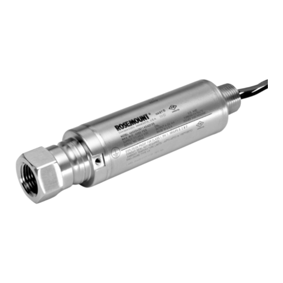
- Page 1 Reference Manual 00809-0100-4022, Rev CA July 2010 Rosemount 4600 Oil & Gas Panel Transmitter www.rosemount.com...
- Page 3 The products described in this document are NOT designed for nuclear-qualified applications. Using non-nuclear qualified products in applications that require nuclear-qualified hardware or products may cause inaccurate readings. For information on Rosemount nuclear-qualified products, contact your local Emerson Process Management. www.rosemount.com...
-
Page 5: Table Of Contents
Reference Manual 00809-0100-4022, Rev CA Rosemount 4600 July 2010 Table of Contents SECTION 1 Using This Manual ........1-1 Service Support . - Page 6 Reference Manual 00809-0100-4022, Rev CA Rosemount 4600 July 2010 TOC-2...
-
Page 7: Using This Manual
July 2010 Section 1 Introduction USING THIS MANUAL The sections in this manual provides information on installing, operating, and maintaining the Rosemount 4600 transmitter. The sections are organized as follows: • Section 2: Installation contains mechanical and electrical installation instructions. -
Page 8: Service Support
To expedite the return process outside of the United States, contact the nearest Emerson Process Management representative. Within the United States, call the Rosemount National Response Center using the 1-800-654-RSMT (7768) toll-free number. This center, available 24 hours a day, will assist you with any needed information or materials. -
Page 9: Overview
Reference Manual 00809-0100-4022, Rev CA Rosemount 4600 July 2010 Section 2 Installation Safety Messages ....... . . page 2-1 General Considerations . -
Page 10: Warnings
Reference Manual 00809-0100-4022, Rev CA Rosemount 4600 July 2010 Warnings Explosions can result in death or serious injury. • Transmitters located in hazardous areas should be installed in accordance with local codes and requirements for that area. • Verify that the operating atmosphere of the transmitter is consistent with the appropriate hazardous locations certifications. - Page 11 Reference Manual 00809-0100-4022, Rev CA Rosemount 4600 July 2010 Figure 2-1. HART Installation Flowchart START HERE Bench Calibration? Field Install (Section 2) Mount Transmitter Configure (page 2-4) Verify (Section 3) Wire Transmitter (pages 2-6–2-9) Confirm Set Units Transmitter Configuration (page 3-5)
-
Page 12: Installation Procedures
Integral conduit seal meets the requirements of NEC 2002 section 501:5 (A) and 501.5 (B). No additional conduit seal is required. NOTE The Rosemount 4600 features a reliable dual process seal design which © meets the requirements of NEC 2002 section 501:5 (F)(3) and API 14F 6.8.2.2. - Page 13 Reference Manual 00809-0100-4022, Rev CA Rosemount 4600 July 2010 Impulse Piping The piping between the process and the transmitter must accurately transfer the pressure to obtain accurate measurements. There are five possible sources of error: pressure transfer, leaks, friction loss (particularly if purging is used), trapped gas in a liquid line and liquid in a gas line.
-
Page 14: Connect Wiring And Power Up
(RFI). Inductive-based transient protectors with more than 3 mH of inductance can adversely affect the output of the Rosemount 4600 transmitter. If your application requires transient protection, it is recommended that you order a transmitter with the transient protection option specified. -
Page 15: Zero The Transmitter
Reference Manual 00809-0100-4022, Rev CA Rosemount 4600 July 2010 Figure 2-3. Power Supply Load Limitations, 4–20 mA Maximum field loop Resistance = 43.5 * (Power Supply Voltage - 11.25) Transmitters 1355 1000 Operating Region 11.25 42.4 Voltage (V dc) *Communication requires a minimum loop resistance of 250 ohms. -
Page 16: Re-Zeroing
3. Verify that the output is 4mA. HAZARDOUS The Rosemount 4600 transmitter has an explosion-proof housing. Individual transmitters are clearly marked with a tag indicating the certifications they LOCATIONS carry. See Appendix B: Approval Information for additional information. -
Page 17: Grounding The Transmitter Case
Methods for grounding the transmitter case include: • Internal Ground Connection: The green lead provides the internal ground connection, and is standard on all Rosemount 4600 transmitters. • External Ground Assembly: This assembly is included with the optional transient protection (Option Code T1). - Page 18 Reference Manual 00809-0100-4022, Rev CA Rosemount 4600 July 2010 2-10...
-
Page 19: Overview
Analog Output Trim: Adjusts the analog output to match the plant standard or the control loop. The Rosemount 4600 uses a microprocessor that contains information about the sensor’s specific characteristics in response to pressure and temperature inputs. A smart transmitter compensates for these sensor variations. The process of generating the sensor performance profile is called factory characterization. -
Page 20: Calibration Overview
• 4–20 mA Output Trim Using Other Scale (page 3-12) Figure 3-1 on page 3-3 illustrates Rosemount 4600 transmitter data flow. Data flow can be summarized in four major steps: 1. A change in pressure is measured by a change in the sensor output (Sensor Signal). - Page 21 00809-0100-4022, Rev CA Rosemount 4600 July 2010 Not all calibration procedures should be performed for each Rosemount 4600 transmitter. Some procedures are appropriate for bench calibration, but should not be performed during field calibration. Table 3-1 identifies the recommended calibration procedures for each type of Rosemount 4600 transmitter for bench or field calibration.
- Page 22 Reference Manual 00809-0100-4022, Rev CA Rosemount 4600 July 2010 Figure 3-2. Rosemount 4600 HART Menu Tree 1. Pressure 2. Percent of Range 1. Device Setup 3. Analog Output 2. PV 4. Sensor Temp. 3. AO 4. PV URV 1. Re-Range 5.
-
Page 23: Determining Calibration Frequency
Step 1: Determine the performance required for your application. Required Performance: 1.1% of span Step 2: Determine the operating conditions. Transmitter: Rosemount 4600G, Range 4 Calibrated Span: 4000 psig Ambient Temperature Change: 50 °F Step 3: Calculate total probable error (TPE). -
Page 24: Choosing A Trim Procedure
Zero trim is zero based, and absolute pressure transmitters reference absolute zero. To correct mounting position effects on a Rosemount 4600 Oil & Gas Transmitter, perform a low trim within the full sensor trim function. The low trim function provides a “zero” correction similar to the zero... -
Page 25: Zero Trim
Reference Manual 00809-0100-4022, Rev CA Rosemount 4600 July 2010 Zero Trim NOTE The transmitter must be within three percent of the span away from zero (for Fast Keys 1, 2, 3, 3, 1 zero-based spans) in order to calibrate with zero trim function. If the zero reading is not within three percent of the true zero, the transmitter will require iterative trims to move the zero within trimmable range. -
Page 26: Full Trim
Reference Manual 00809-0100-4022, Rev CA Rosemount 4600 July 2010 Full Trim NOTE Use a pressure input source that is at least three times more accurate than Fast Keys 1, 2, 3, 3 the transmitter, and allow the input pressure to stabilize for ten seconds before entering any values. -
Page 27: Recall Factory Trim
Reference Manual 00809-0100-4022, Rev CA Rosemount 4600 July 2010 RECALL FACTORY TRIM The Recall Factory Trim commands allow the restoration of the as-shipped factory settings of the sensor trim and analog output trim. Recall Factory Trim— This command resets the transmitter sensor trim to the “as shipped” factory settings. -
Page 28: Analog Output Trim
Reference Manual 00809-0100-4022, Rev CA Rosemount 4600 July 2010 ANALOG OUTPUT TRIM The Analog Output Trim commands allow you to adjust the transmitter’s current output at the 4 and 20 mA points to match the plant standards. This command adjusts the digital to analog signal conversion (see Figure 3-1 on page 3-3). - Page 29 Reference Manual 00809-0100-4022, Rev CA Rosemount 4600 July 2010 Right click on the device and select “Calibrate,” then “D/A Trim” from the menu 1. Click Next after setting the control loop to manual. 2. Click Next after connecting the reference meter.
-
Page 30: Digital-To-Analog Trim Using Alternate Scale
Reference Manual 00809-0100-4022, Rev CA Rosemount 4600 July 2010 Digital-to-Analog Trim The Scaled D/A Trim command matches the 4 and 20 mA points to a user selectable reference scale other than 4 and 20 mA (for example, 1 to 5 volts if... -
Page 31: Overview
Reference Manual 00809-0100-4022, Rev CA Rosemount 4600 July 2010 Section 4 Troubleshooting Overview ........page 4-1 Safety Messages . - Page 32 Reference Manual 00809-0100-4022, Rev CA Rosemount 4600 July 2010 Table 4-1. Rosemount 4600 troubleshooting table Symptom Corrective Actions Transmitter milliamp reading is zero Verify power is applied to signal terminals Check power wires for reversed polarity Verify terminal voltage is 11.25 to 42.4 V dc...
-
Page 33: Ordering Information
ORDERING INFORMATION Table 1. Rosemount 4600 Oil and Gas Pressure Transmitter Ordering Information ★ The Standard offering represents the most common options. The starred options (★) should be selected for best delivery. __The Expanded offering is subject to additional delivery lead time. -
Page 34: Options (Include With Selected Model Number
★ Prior-use certificate of FMEDA data Typical Model Number: 4600 G 4 2 E11 A 5A D1 E5 (1) Materials of Construction comply with recommendations per NACE MR0175/ISO 15156 for sour oilfield production environments. Environmental limits apply to certain materials. Consult latest standard for details. Selected materials also conform to NACE MR0103 for sour refining environments. -
Page 35: Specifications
Reference Manual 00809-0100-4022, Rev CA Rosemount 4600 July 2010 SPECIFICATIONS Performance For zero-based spans, reference conditions, silicone oil fill, SST materials, in.- 14 NPT process connections, digital trim values set to equal range Specifications points. Does not include any error due to the effects of sealed gauge. -
Page 36: Functional Specifications
Reference Manual 00809-0100-4022, Rev CA Rosemount 4600 July 2010 Functional Range and Sensor Limits Specifications Rosemount 4600 Oil & Gas Panel Transmitter Range Limits Range 2 Range 4 Span Range 5 Range 6 Units min. max. min. max. min. max. - Page 37 Reference Manual 00809-0100-4022, Rev CA Rosemount 4600 July 2010 Load Limitations Maximum loop resistance is determined by the voltage level of the external power supply, as described by: Max. Loop Resistance = 43.5 (Power Supply Voltage – 11.25) 1355 1000...
-
Page 38: Physical Specifications
Failure Mode Alarm HART 4-20mA (output code A) If self-diagnostics detect a gross transmitter failure, the analog signal will be driven offscale to alert the user. Rosemount standard and custom alarm levels are available. High or low alarm signal is software-selectable. - Page 39 FM, a nationally recognized testing laboratory (NRTL) as accredited by the Federal Occupational Safety and Health Administration (OSHA). Shipping Weights for Rosemount 4600 Range 2 and 4: 1.34 lb. (0,61 kg) Range 5 and 6: 2.03 lb. (0,92 kg)
-
Page 40: Dimensional Drawings
Reference Manual 00809-0100-4022, Rev CA Rosemount 4600 July 2010 DIMENSIONAL DRAWINGS Figure A-1. Dimensional Drawings Range 2 and 4 Range 2 and 4 with T1 Ordering Option Electrical Connection Electrical ½–14 NPT Connection ½–14 NPT (180,3) (167,6) Optional Ground Screw... - Page 41 Reference Manual 00809-0100-4022, Rev CA Rosemount 4600 July 2010 Figure A-2. Dimensional Drawings Range 5 and 6 Range 5 and 6 with T1 Ordering Option Electrical Electrical Connection Connection ½–14 NPT ½–14 NPT 7.17 (182,1) (169,5) Optional Optional Ground Ground...
- Page 42 Reference Manual 00809-0100-4022, Rev CA Rosemount 4600 July 2010 A-10...
-
Page 43: Approved Manufacturing Locations
Federal Occupational Safety and Health Administration (OSHA). European Directive The EC declaration of conformity for all applicable European directives for this product can be found on the Rosemount website at Information www.emersonprocess.com. A hard copy may be obtained by contacting our local sales office. -
Page 44: Hazardous Locations Certifications
T5 (T = -20°C to 40°C); Suitable for Class I, Division 2, Groups A, B, C, and D, when installed per Rosemount drawing 04620-5005; Enclosure Type 4X Conduit seal not required Intrinsically Safe for use in Class I, Division 1, Groups A, B, C, and D;... - Page 45 The Rosemount 4600 Pressure transmitter is provided with a permanently connected unterminated cable. The free end of the cable shall be connected using a suitable junction box, e.g. in type of explosion...
- Page 46 The Rosemount 4600 Pressure transmitter is provided with a permanently connected unterminated cable. The free end of the cable shall be connected using a suitable junction box, e.g. in type of explosion protection flameproof enclosure "d"...
- Page 47 Reference Manual 00809-0100-4022, Rev CA Rosemount 4600 July 2010...
- Page 48 Reference Manual 00809-0100-4022, Rev CA Rosemount 4600 July 2010...
- Page 49 Reference Manual 00809-0100-4022, Rev CA Rosemount 4600 July 2010...
- Page 50 Reference Manual 00809-0100-4022, Rev CA Rosemount 4600 July 2010...
- Page 51 Reference Manual 00809-0100-4022, Rev CA Rosemount 4600 July 2010...
- Page 52 Reference Manual 00809-0100-4022, Rev CA Rosemount 4600 July 2010 B-10...
- Page 53 Reference Manual 00809-0100-4022, Rev CA Rosemount 4600 July 2010 B-11...
- Page 54 Reference Manual 00809-0100-4022, Rev CA Rosemount 4600 July 2010 B-12...
- Page 55 Reference Manual 00809-0100-4022, Rev CA Rosemount 4600 July 2010 B-13...
- Page 56 Reference Manual 00809-0100-4022, Rev CA Rosemount 4600 July 2010 B-14...
- Page 57 Reference Manual 00809-0100-4022, Rev CA Rosemount 4600 July 2010 Index ... . .4-1 Troubleshooting ..4-2 Reference table ..3-10 .
- Page 58 Reference Manual 00809-0100-4022, Rev CA Rosemount 4600 July 2010 Index-2...
- Page 60 Rosemount 4600 July 2010 Standard Terms and Conditions of Sale can be found at www.rosemount.com\terms_of_sale The Emerson logo is a trade mark and service mark of Emerson Electric Co. Rosemount and the Rosemount logotype are registered trademarks of Rosemount Inc.
Need help?
Do you have a question about the 4600 and is the answer not in the manual?
Questions and answers