Page 1
Reference Manual 00809-0100-4835 Rev BD July 2016 
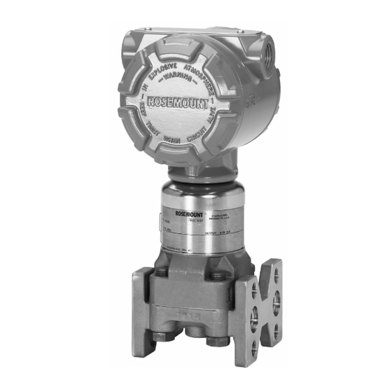
Rosemount 3150 Series Nuclear Pressure Transmitters including the Rosemount 3152, 3153 and 3154...
Page 3
For Assistance: Within the United States, contact Rosemount Nuclear Instruments, Inc. at 1-952-949-5210. Outside the United States, contact the nearest Rosemount representative.
Page 4
July 2016 Rosemount Nuclear Instruments, Inc. Warranty and Limitations of Remedy The warranty and limitations of remedy applicable to this Rosemount equipment are as stated on the reverse side of the current Rosemount quotation and customer acknowledgment forms. RETURN OF MATERIAL Authorization for return is required from Rosemount Nuclear Instruments, Inc.
Page 5
Reference Manual 00809-0100-4835 Rev BD Rosemount 3150 Series July 2016 Revision Status Changes from March 2015 (Rev BC) to July 2016 (Rev BD) Page Page Changes (Rev BC) (Rev BD) Cover, Cover, Document revision change from March 2015 to July 2016, Rev BC to Rev BD...
Page 6
Reference Manual 00809-0100-4835 Rev BD Rosemount 3150 Series July 2016...
Reference Manual 00809-0100-4835 Rev BD Rosemount 3150 Series July 2016 Table of Contents SECTION 1 Using this Manual..........1-1 Introduction Overview .
Page 8
Reference Manual 00809-0100-4835 Rev BD Rosemount 3150 Series July 2016 SECTION 4 Overview ..........
USING THIS MANUAL maintaining the Rosemount 3150 Series Pressure Transmitters. Instructions for the 3152, 3153 and 3154 models are included in this manual. Where differences in instructions between the models occur they shall be noted within those instructions. The manual is organized...
Page 10
Reference Manual 00809-0100-4835 Rev BD Rosemount 3150 Series July 2016...
• Use only components supplied with the Rosemount 3152, 3153 or 3154 transmitter or designated by Rosemount Nuclear Instruments, Inc. as spare parts for the 3152, 3153 or 3154. Improper assembly of mounting bracket to traditional process flange can damage sensor module.
Page 13
Two mounting options are qualified for the transmitter: panel mount or 2-inch pipe mount. A stainless steel panel bracket is provided with the 3154. For the 3152 and 3153 series, the user has the option of specifying either the stamped carbon steel panel bracket or the stainless steel panel bracket.
Reference Manual 00809-0100-4835 Rev BD Rosemount 3150 Series July 2016 Mount the process flanges with sufficient clearance for process connections. For safety reasons, place the drain/vent valves so the process fluid is directed away from possible human contact when the vents are used.
Reference Manual 00809-0100-4835 Rev BD Rosemount 3150 Series July 2016 Figure 2-1 – Swagelok™ Compression Fitting Detail Dimensions are nominal in inches (mm) The Swagelok™ tube fittings come completely assembled and are ready for immediate use. Do not disassemble them before use because dirt or foreign materials may get into the fitting and cause leaks.
Reference Manual 00809-0100-4835 Rev BD Rosemount 3150 Series July 2016 • Use impulse piping of large enough diameter to avoid friction effects and blockage • Vent all gas from liquid piping legs • Vent all liquid from gas piping legs •...
Use your plant-approved, qualified thread sealant on the conduit connection threads. IMPORTANT For all 3152 and 3153 transmitters, install the conduit plug (provided with the transmitter) in the unused conduit opening per the torque values outlined in Section 5: Maintenance and Troubleshooting, Table 5-2.
CONSIDERATIONS carefully before proceeding to the electrical installation procedure. Rosemount 3150 Series transmitters provide a 4-20 mA signal when connected to a suitable dc power source. Figure 2-3 illustrates a typical signal loop consisting of a transmitter, power supply, and various receivers (controller, indicator, computer).
Page 19
Reference Manual 00809-0100-4835 Rev BD Rosemount 3150 Series July 2016 Figure 2-4 – Transmitter Supply Voltage vs. Load Figure 2-4a – IEEE Qualified and Design Regions (applicable to 3152N, 3153N and 3154N models only) 2500 DESIGN REGION 2150 IEEE 2000...
Page 20
(floating) or grounded at any one point in the signal loop. For installations with EMC performance requirements, consult the Rosemount Nuclear Instruments, Inc. EMC test reports for additional details regarding recommended practices for electrical wiring per various national and international codes and regulations.
Figure 2-5). Please note that the bolts required for this step are customer supplied hardware. Based on qualification tests performed by Rosemount, the bolts listed in Table 2-1 are recommended for the bracket- to-customer interface. Torque each bolt to value shown in Table 5-2 in Section 5 Maintenance and Troubleshooting.
Page 22
(3) Bracket Codes 2 and 7 are available on the 3152, 3153 and 3154-series (4) Bracket Codes 3 and 8 are available on the 3152, 3153 and 3154-series; this bracket code includes the listed bracket along with the pipe mount hardware (Rosemount P/N 01154-0044-0001)
Page 23
Reference Manual 00809-0100-4835 Rev BD Rosemount 3150 Series July 2016 (1) (2) Figure 2-5 – Typical Transmitter Mounting Bracket Configuration, Traditional Flange NOTE: All dimensions are nominal in inches (millimeters) (1) Transmitter and bracket orientation with respect to gravity will not impact qualification.
Page 24
Reference Manual 00809-0100-4835 Rev BD Rosemount 3150 Series July 2016 Figure 2-6 – Transmitter Dimensional Drawings 3152, 3153 Traditional Flange NOTE: All dimensions are nominal in inches (millimeters) 3154 Traditional Flange NOTE: All dimensions are nominal in inches (millimeters) 2-14...
Reference Manual 00809-0100-4835 Rev BD Rosemount 3150 Series July 2016 Mechanical – Conduit CAUTION Be careful not to damage the set screw interface between the sensor module and the electronics housing. NOTE Install the conduit seal in accordance with the manufacturer’s instructions or use the procedure in this section.
Reference Manual 00809-0100-4835 Rev BD Rosemount 3150 Series July 2016 SECTION 3: CALIBRATION Overview........
Page 29
• Use only components supplied with the 3152, 3153 or 3154 transmitter or designated by Rosemount Nuclear Instruments, Inc. as spare parts for the 3152, 3153 or 3154.
Reference Manual 00809-0100-4835 Rev BD Rosemount 3150 Series July 2016 Definitions The following definitions and descriptions are provided to aid in calibration: Differential pressure between the high pressure “H” and low pressure “L” process inputs, as marked on the transmitter module.
Page 31
Reference Manual 00809-0100-4835 Rev BD Rosemount 3150 Series July 2016 Figure 3-1 – Zero and Span Zero and Span Adjustment Screws Electronics Assembly located inside electronics housing Figure 3-2 – Electronics Assembly Coarse Zero Damping Adjustment Select Jumper (optional)
Reference Manual 00809-0100-4835 Rev BD Rosemount 3150 Series July 2016 Span Adjustment Range For transmitter ranges 2 to 6, the span is continuously adjustable to allow calibration anywhere between the transmitter URL and 1/10 of URL. For example, the span on a Range 2 transmitter can be...
00809-0100-4835 Rev BD Rosemount 3150 Series July 2016 CALIBRATION PROCEDURES The following calibration procedures describe the recommended steps necessary to calibrate the Rosemount 3150 Series pressure transmitters. Span and Zero Adjustment CAUTION The 3150 Series pressure transmitters contain electronic circuit boards which may be static sensitive.
Page 34
Reference Manual 00809-0100-4835 Rev BD Rosemount 3150 Series July 2016 Figure 3-4a – Example for Zero Based Range 2 for a calibration of 0 to 100 inH O (100 inH O span) Calibration (English Units) Adjust the zero: With 0 inH O applied to the transmitter, turn the Zero adjustment until the transmitter reads 4 mA.
Reference Manual 00809-0100-4835 Rev BD Rosemount 3150 Series July 2016 Figure 3-5a – Example for Elevated Range 2 with Zero Elevation for a calibration of –120 to –20 Zero Calibration (English Units) O (100 inH O span) Calibrate the transmitter to 0 to 100 inH O as described in the Zero Based Calibration Procedure.
Page 36
Reference Manual 00809-0100-4835 Rev BD Rosemount 3150 Series July 2016 Figure 3-6a – Example for Suppressed Range 2 with Zero Suppression for a calibration of 20 to 120 Zero Calibration (English Units) O (100 inH O span) Calibrate the transmitter to 0 to 100 inH O as described in the Zero Based Calibration Procedure.
Reference Manual 00809-0100-4835 Rev BD Rosemount 3150 Series July 2016 Coarse Zero Select Jumper The Coarse Zero Select Jumper (see Figure 3-2) is shipped from the Position Selection Procedure factory in either the Nominal position or the position required to obtain the calibration specified when ordered.
Damping Adjustment The 3150 Series amplifier boards for transmitter output code options B (3152) and T (3153 and 3154) are designed to permit damping of rapid pulsations in the pressure source through adjustment of the single turn damping adjustment potentiometer (see Figure 3-2).
Correction for High Static Line Pressure High Static Line Pressure Span Rosemount 3150 Series Range 1, 2, and 3 differential pressure Effect on Range Codes 1, 2 and 3 transmitters do not require correction for high static pressure span DP Transmitters effect.
Page 40
Reference Manual 00809-0100-4835 Rev BD Rosemount 3150 Series July 2016 Figure 3-8 outlines examples of calculating a High Static Line Pressure Span Correction using Method 1. Figure 3-8a uses English units (psi) while Figure 3-8b uses SI units (MPa). Range 4; for a calibration of –10 to 45 psi corrected for 1,500 psi static Figure 3-8a –...
Page 41
Reference Manual 00809-0100-4835 Rev BD Rosemount 3150 Series July 2016 High Static Line Pressure Span Method 2 for High Static Line Pressure, Ranges 4 and 5 Correction for Range Code 4 and 5 DP Transmitters (continued) Adjust transmitter pressure input while leaving the output at 4 mA and 20 mA.
Page 42
Reference Manual 00809-0100-4835 Rev BD Rosemount 3150 Series July 2016 Figure 3-9a – Example 1 for High Range 4 for a calibration of 0 to 45 psi corrected for 1,500 psi static line pressure Static Line Pressure, Span Correction using Method 2 (English Units) In this example LRV is 0 psid.
Page 43
Reference Manual 00809-0100-4835 Rev BD Rosemount 3150 Series July 2016 Figure 3-10a – Example 2 for High Range 5 for a calibration of –250 to 750 psi corrected for 1,500 psi static line pressure Static Line Pressure, Span Correction using Method 2 (English Units) Calculate the corrected LRV pressure input = -250 psi –...
Reference Manual 00809-0100-4835 Rev BD Rosemount 3150 Series July 2016 High Static Line Pressure Zero Zero shift with static pressure is not systematic. However, the effect Correction for Differential Pressure can be eliminated during calibration. To trim out the zero error at high...
Page 45
Reference Manual 00809-0100-4835 Rev BD Rosemount 3150 Series July 2016 3-18...
Reference Manual 00809-0100-4835 Rev BD Rosemount 3150 Series July 2016 TRANSMITTER THEORY OF The block diagram in Figure 4-1 illustrates the operation of the 3150 series pressure transmitter. OPERATION The 3150 series pressure transmitters have a variable capacitance sensor (see Figure 4-2). Differential capacitance between the sensing...
Reference Manual 00809-0100-4835 Rev BD Rosemount 3150 Series July 2016 Figure 4-1 Block Diagram Process pressure is transmitted through an isolating diaphragm and THE SENSOR CELL silicon oil fill fluid to a sensing diaphragm in the center of the Sensor.
Reference Manual 00809-0100-4835 Rev BD Rosemount 3150 Series July 2016 Capacitor Plates Silicon Oil Rigid Insulation Center Diaphragm Isolating Diaphragms The demodulator consists of a diode bridge that rectifies the ac signal DEMODULATOR from the sensor cell to a dc signal. The oscillator driving current, I...
Reference Manual 00809-0100-4835 Rev BD Rosemount 3150 Series July 2016 The oscillator frequency is determined by the capacitance of the OSCILLATOR sensing element and the inductance of the transformer windings. The sensing element capacitance is variable. Therefore, the frequency is variable about a nominal value of 110kHz.
Page 51
Reference Manual 00809-0100-4835 Rev BD Rosemount 3150 Series July 2016...
Reference Manual 00809-0100-4835 Rev BD Rosemount 3150 Series July 2016 SECTION 5: MAINTENANCE & TROUBLESHOOTING Overview ........
Page 53
• Use only components supplied with the 3152, 3153 or 3154 transmitter or designated by Rosemount Nuclear Instruments, Inc. as spare parts for the 3152, 3153 or 3154.
Reference Manual 00809-0100-4835 Rev BD Rosemount 3150 Series July 2016 The Rosemount 3150 Series transmitters have no moving parts and GENERAL CONSIDERATIONS require a minimum of scheduled maintenance. Calibration procedures for range adjustments are outlined in Section 3 Calibration. A...
Page 55
Reference Manual 00809-0100-4835 Rev BD Rosemount 3150 Series July 2016 Figure 5-1 – Parts Drawing, Exploded View Table 5-1 – 3150 Series Parts List ITEM # DESCRIPTION ITEM # DESCRIPTION Electronics Cover Sensor Module O-ring for Electronics Cover C-rings for Process Flange...
To install the new electronics assembly, refer to the steps outlined in Electrical Housing Reassembly section. If this procedure reveals a malfunctioning assembly, return the defective assembly to Rosemount Nuclear Instruments, Inc. for replacement. See Notices regarding field repair at the beginning of this manual.
NOTE Results obtained using the above procedure may vary depending on the specific meter that is used for testing (manufacturer, model, type, etc.). Please contact Rosemount Nuclear Instruments, Inc. with any questions regarding test procedure and/or results. RESISTANCE CHECK Using a low-voltage ohmmeter, check resistance between the following sensor module pins: A.
Reference Manual 00809-0100-4835 Rev BD Rosemount 3150 Series July 2016 Figure 5-2 – Sensor Module Pin Connections MODULE HOUSING NOTE DISSASSEMBLY Before removing the transmitter from service: PROCEDURE • Follow all plant safety rules and procedures. • Isolate and vent the process from the transmitter before removing the transmitter from service.
266) applied at the factory during manufacturing. If this interface is damaged, the qualification of the transmitter becomes invalid. For any maintenance that requires the sensor module (8) be removed from the housing (5), please contact Rosemount Nuclear Instruments, Inc.
Page 60
Reference Manual 00809-0100-4835 Rev BD Rosemount 3150 Series July 2016 Figure 5-3 – Location of Zero and Span Adjustment Screws and Electronics Assembly Captive Screws Two 6-32 Screws Ensure potentiometers and adjustment screws are aligned while removing electronics Figure 5-4 – Removing Electronics Assembly...
Page 61
Reference Manual 00809-0100-4835 Rev BD Rosemount 3150 Series July 2016 Figure 5-5 – Removing Terminal Block Assembly Two 6-32 Screws 5-10...
The following reassembly instructions assume that the housing-to-module interface is intact. For any maintenance that requires the sensor module (8) be removed from the housing (5), please contact Rosemount Nuclear Instruments, Inc. Preliminary 1. Replace the cover o-rings (2) whenever removing an electronics housing cover (1).
Page 63
Rosemount 3150 Series July 2016 2. Verify connector plug o-ring is in place as shown in Figure 5-7. If connector plug o-ring is missing, please contact Rosemount Nuclear Instruments, Inc. for assistance. ® 3. Apply a small amount of Molykote...
Page 64
Reference Manual 00809-0100-4835 Rev BD Rosemount 3150 Series July 2016 Figure 5-9 – Installation of Electronics Assembly Connector Plug Ensure these two clips are fully engaged under lip of sensor module 5. Push the electronics assembly (4) into the electronics housing (5) and fasten with the two 6-32 captive screws.
Reference Manual 00809-0100-4835 Rev BD Rosemount 3150 Series July 2016 Electronics Housing Cover 1. Inspect the housing (5) and cover (1) threads to ensure they are Installation free of foreign material. If foreign material is present, remove it. NOTE Use of thread lubricant on the cover is recommended to reduce galling between the cover and housing.
Page 66
Reference Manual 00809-0100-4835 Rev BD Rosemount 3150 Series July 2016 With the process flange sitting secure on the sensor module, install two flange cap screws (13) into the flange location shown in Figure 5-12. Tighten the cap screws approximately two or three rotations only.
Reference Manual 00809-0100-4835 Rev BD Rosemount 3150 Series July 2016 POST-ASSEMBLY TESTS 1. Conduct hydrostatic testing to 150% of maximum working pressure or 2,000 psi (13.79 MPa), whichever is greater. Conduct the testing for a duration of ten minutes minimum, and...
Page 68
Sensor Module See Disassembly Procedure for instructions on disassembly. Check for obvious defects (i.e. punctured isolating diaphragm, etc.) and contact Rosemount Nuclear Instruments, Inc. Power Supply Check the power supply output voltage at the transmitter. Check the insulation and condition of primary element.
Page 69
Sensor Module See Disassembly Procedure for instructions on disassembly. Check for obvious defects (i.e. punctured isolating diaphragm, etc.) and contact Rosemount Nuclear Instruments, Inc. Power Supply Check the power supply output voltage at the transmitter. CAUTION...
Page 70
Reference Manual 00809-0100-4835 Rev. BD Rosemount 3150 Series July 2016 5-19...
Transmitter Spare Parts List ..... . page 6-4 This section provides information pertaining to the spare part kits OVERVIEW offering for Rosemount model 3152, 3153 and 3154 Transmitters. Techniques for transmitter troubleshooting and methods for disassembly and reassembly are provided in Section 5. •...
• Use only components supplied with the 3152, 3153 or 3154 transmitter or designated by Rosemount Nuclear Instruments, Inc. as spare parts for the 3152, 3153 or 3154.
Page 73
Rosemount Nuclear Instruments, Inc. approved installation and calibration procedures herein. NOTE Spare parts for Rosemount 3152, 3153 and 3154 models are not hydrostatically tested or nuclear cleaned. NOTE The part numbers shown are current at the time of printing of this manual, but may be revised in the future.
Page 74
Reference Manual 00809-0100-4835 Rev BD Rosemount 3150 Series July 2016 Spare parts list for Rosemount 3152, 3153 and 3154 model TRANSMITTER SPARE PARTS transmitters. LIST Spare Parts Category Quantity Required Item Number Rosemount Order Number Part Description Transmitter: Electronics 3152N Electronics Assembly, Output Code A...
Page 75
Reference Manual 00809-0100-4835 Rev BD Rosemount 3150 Series July 2016 Spare Parts Category Quantity Required Item Number Rosemount Order Number Part Description Process Flange Kits for DP Transmitters Flange Assembly w/Qty (2) C-rings: Flange Code F0 9,10 03154-5022-1001 Flange Assembly w/Qty (2) C-rings: Flange Code F1...
Page 76
03154-5025-0001 (1) Rosemount recommends one spare or kit for every 25 transmitters in Category “A”, one spare part or kit for every 50 transmitters in Category “B”, and one spare part or kit for every 5 transmitters in Category “C”.
Page 77
Reference Manual 00809-0100-4835 Rev BD Rosemount 3150 Series July 2016 Page Intentionally Left Blank...
Page 78
Reference Manual 00809-0100-4835 Rev BD Rosemount 3150 Series July 2016 Page Intentionally Left Blank...
Page 79
Reference Manual 00809-0100-4835 Rev BD Rosemount 3150 Series July 2016 Page Intentionally Left Blank...
Need help?
Do you have a question about the 3152 and is the answer not in the manual?
Questions and answers