Advertisement
Quick Links
Advertisement

Related Manuals for Shuttle TNT


Summary of Contents for Shuttle TNT
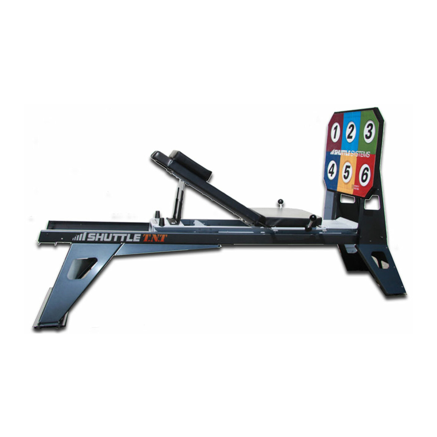
- Page 1 Training ‘n’ Therapy Leg Press ASSEMBLY GUIDE MADE IN THE USA ...
- Page 2 Visit this link to watch the Shuttle TNT Assembly Guide: oo.gl/9LNIa7 The Shuttle TNT is shipped in two boxes. Unpack both boxes and use the checklist below to identify parts. 7/16” and ½“ Wrench required for this assembly. Two people are required to complete assembly. Please Note: T he parts have numbers to assist assembly by matching like numbers. Nuts and bolts are in the appropriate position finger tight. First you remove the respective bolts and nuts then match the parts. Reinsert the bolts in the matched parts and lightly tighten the bolts and nuts. (The bolts and nuts should be oriented as they were in the parts when received). BOX 1 Contains: 1) Carriage 4)Plastic Nut Caps for 5/16 nuts. 1) Rail Assembly Several spare bolts and nuts are included. 1) Headrest 1) ¼” Allen Wrench **MODELS WITH TOWERS** 1) 5/16” Allen Wrench 1) Tower Cross Bar 1) Seat and Handle Grip Assembly 2) Towers with pulleys and ropes BOX 2 Contains: 1) Kickplate Stand 1) Rail Wings 1) Head End Stand 1) Kickplate 1) Head End Stand Base Plate ...
- Page 3 4) Turn the Rails over. ( 2 people recommended) 5) Add R ail Wings to Rails by matching numbered hole sets 1 & 2. 6) Secure using the small Allen wrench and a 7/16” wrench. 7) Place the H ead End Stand on the R ails aligning the number 3 & 4. T he four bolts and nuts must be removed and reinstalled through the four appropriate holes. Lightly tighten bolts to be tightened in next step. Page 3 Owner’s Manual V1.0 © 2016 Shuttle Systems Inc. All Rights Reserved ...
- Page 4 8) Place the h eadend stand base plate with the rubber feet onto the the stand structure with the feet pointing up and match the 5 & 6. Tighten all nuts on the W ings and S tand . 9) Turn the rail frame with the head end stand attached upright. ( 2 people recommended) Page 4 Owner’s Manual V1.0 © 2016 Shuttle Systems Inc. All Rights Reserved ...
- Page 5 Place the kickplate frame up to the foot end of the rail frame. Remove the eight bolts and set them aside being aware of orientation with the head of the bolts inboard on the rails and the nuts outboard on the four rear bolts. Use the larger Allen wrench and ½ inch wrench. Page 5 Owner’s Manual V1.0 © 2016 Shuttle Systems Inc. All Rights Reserved ...
- Page 6 Place the rail frame on the horizontal plate in the middle of the kickplate assembly. M atch 7 and 8. Insert the 8 bolts and nuts and tighten. Check all bolts and nuts for tightness. Replace the four black plastic nut covers. Place the seat on the carriage matching the 13 & 14. Remove the 4 nuts and washers from under the seat and secure the seat to the carriage rails through the handle bar and through the matching holes on the carriage. Page 6 Owner’s Manual V1.0 © 2016 Shuttle Systems Inc. All Rights Reserved ...
- Page 7 The hole in the front center of the curved handle structure should be placed over the bolt on the foot rest. Add the nut, tighten, then add black nut cover. Page 7 Owner’s Manual V1.0 © 2016 Shuttle Systems Inc. All Rights Reserved ...
- Page 8 Attach the kickplate onto the kickplate frame by removing the four aluminum knobs and reattach them after placing the kickplate at the desired height. Insert the Carriage into the head end of the rails. Look for loose bolts or nuts left on the rails. L ubricate the wheels and tracks lightly with WD 40 if squeaks should occur. Attach the various elasticords by pulling and lifting each lanyard vertically a few inches and pulling until a white plastic disk appears. Secure each of the elasticords into the appropriate slot under the head end of the carriage. Page 8 Owner’s Manual V1.0 © 2016 Shuttle Systems Inc. All Rights Reserved ...
- Page 9 To use the shuttle as a leg press, lift the backrest up and rotate the black hinged support plate at the rear of the carriage up to secure it between the two black rubber stops located under the back rest. This will achieve a backrest angle of 45 degrees. Add the H eadrest . Place the red R ange of Motion Control Rope with the round ball on end in the black plastic clam cleat rope lock located at the head end stand. This rope is used to adjust the start point of the carriage travel and provides a soft stop at the foot end of the travel. Page 9 Owner’s Manual V1.0 © 2016 Shuttle Systems Inc. All Rights Reserved ...
- Page 10 Reinstall the two black rubber carriage travel limiter stops at the end of the rail. PNF PULLEY SYSTEM INSTALLATION: Shuttles that include the towers and pulley system the following apply. 1) Place the Headend Stand on a box to elevate the machine. 2) Orient the 32 inch long tower cross bar aligning the 9 & 10 . Page 10 Owner’s Manual V1.0 © 2016 Shuttle Systems Inc. All Rights Reserved ...
- Page 11 3) Secure with the two bolts and nuts in the same orientation as received. 4) Matching the 11 & 12 with the stand base. Secure the towers with the crossbar and the base plate with the bolts and nuts provided. Page 11 Owner’s Manual V1.0 © 2016 Shuttle Systems Inc. All Rights Reserved ...
- Page 12 5) Unravel the pulley ropes and secure the free end of the pulley ropes to the black plastic clam cleat rope locks at each rear edge of the seat pad. Page 12 Owner’s Manual V1.0 © 2016 Shuttle Systems Inc. All Rights Reserved ...
- Page 13 How to Replace Elasticords: 1) Loosen one bolt near the footend of the Shuttle TNT under the kickplate. This will release the plate holding in the elasticords. 2) Once the bracket has been loosened elasticords can be removed from the slotted plate. 3) To completely remove elasticord move to the headend of the machine and loosen the rod holding the loop end of the elastic in place. Page 13 Owner’s Manual V1.0 © 2016 Shuttle Systems Inc. All Rights Reserved ...
- Page 14 4) Once you string the new elasticord through the rod, pull all 8 elasticords tight. Please call us if you have any questions. (800)3345633 Shuttle Systems Page 14 Owner’s Manual V1.0 © 2016 Shuttle Systems Inc. All Rights Reserved ...
Need help?
Do you have a question about the TNT and is the answer not in the manual?
Questions and answers