Table of Contents
Advertisement
Quick Links
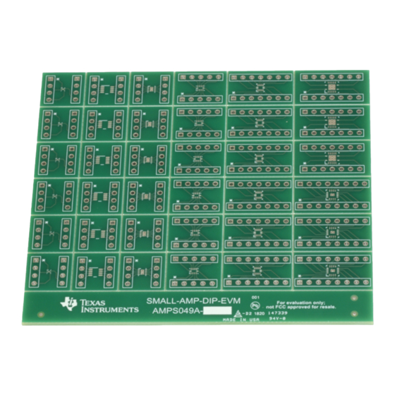
This user's guide contains support documentation for the SMALL-AMP-DIP evaluation module (EVM).
Included is a step-by-step guide on setting up and configuring the EVM, bill of materials (BOM), and
printed circuit board (PCB) layout.
...................................................................................................................
1
2
3
EVM Description and PCB Layout
4
Bill of Materials and References
1
2
3
SMALL-AMP-DIP Evaluation Module (EVM)
..............................................................................................................
.........................................................................................
.........................................................................................
List of Figures
.............................................................................................
.........................................................................................................
...........................................................................................
Copyright © 2019, Texas Instruments Incorporated
Contents
SMALL-AMP-DIP Evaluation Module (EVM)
User's Guide
SBOU215 - January 2019
3
4
7
10
4
5
5
1
Advertisement
Table of Contents

Related Manuals for Texas Instruments SMALL-AMP-DIP


Summary of Contents for Texas Instruments SMALL-AMP-DIP
-
Page 1: Table Of Contents
SBOU215 – January 2019 SMALL-AMP-DIP Evaluation Module (EVM) This user’s guide contains support documentation for the SMALL-AMP-DIP evaluation module (EVM). Included is a step-by-step guide on setting up and configuring the EVM, bill of materials (BOM), and printed circuit board (PCB) layout. - Page 2 RTE package top layer (left) and bottom layer (right) PCB layout List of Tables ..................... Package type mapped to EVM Trademarks All trademarks are the property of their respective owners. SMALL-AMP-DIP Evaluation Module (EVM) SBOU215 – January 2019 Submit Documentation Feedback Copyright © 2019, Texas Instruments Incorporated...
-
Page 3: Introduction
Introduction The SMALL-AMP-DIP-EVM is designed to facilitate evaluation of op amps offered in small packages. This EVM gives users an easy tool to test the following op amp packages: DPW, DCN, DDF, DSG, RUG, RUC, RGY, and RTE. This EVM routes each pin of the device to a header pin and can be used as a basic building block for circuit design and device testing purposes. -
Page 4: Hardware Setup
Hardware Setup www.ti.com Hardware Setup The SMALL-AMP-DIP-EVM setup requires identifying and breaking out the desired PCB from the EVM and then soldering the IC and terminal strips onto the EVM. This section presents the details of these procedures. EVM Package Locations... -
Page 5: Detach Desired Pcb
For the RUC and RGY packages, use 7 position lengths. • And for the RTE package, use 8 position lengths. Figure 4. Terminal strip (TS-132-G-AA) broken into 4 position length SBOU215 – January 2019 SMALL-AMP-DIP Evaluation Module (EVM) Submit Documentation Feedback Copyright © 2019, Texas Instruments Incorporated... -
Page 6: Terminal Strip (Ts-132-G-Aa) Inserted Into Spare Dip Socket
6. Position the separated PCB with the soldered IC over the terminal strips and solder each pin in place. Carefully remove the PCB from the DIP socket. Figure 6 displays a fully assembled PCB. Figure 6. Fully assembled PCB SMALL-AMP-DIP Evaluation Module (EVM) SBOU215 – January 2019 Submit Documentation Feedback Copyright © 2019, Texas Instruments Incorporated... -
Page 7: Dpw Package Top Layer (Left) And Bottom Layer (Right) Pcb Layout
Figure 9. DCN and DDF packages top layer (left) and bottom layer (right) PCB layout The SOT-23 (DCN and DDF) package has the following dimensions: 0.65-mm pin pitch, 1.1-mm maximum height, 2.9-mm length, and 1.63-mm width. SBOU215 – January 2019 SMALL-AMP-DIP Evaluation Module (EVM) Submit Documentation Feedback Copyright © 2019, Texas Instruments Incorporated... -
Page 8: Rug Package Top Layer (Left) And Bottom Layer (Right) Pcb Layout
Figure 11. RUC package top layer (left) and bottom layer (right) PCB layout The X2QFN (RUC) package has the following dimensions: 0.4-mm pin pitch, 0.35-mm maximum height, 2.0-mm length, and 2.0-mm width SMALL-AMP-DIP Evaluation Module (EVM) SBOU215 – January 2019 Submit Documentation Feedback Copyright © 2019, Texas Instruments Incorporated... -
Page 9: Rgy Package Top Layer (Left) And Bottom Layer (Right) Pcb Layout
Figure 13. RTE package top layer (left) and bottom layer (right) PCB layout The WQFN (RTE) package has the following dimensions: 0.5-mm pin pitch, 0.75-mm maximum height, 3.0-mm length, and 3.0-mm width. SBOU215 – January 2019 SMALL-AMP-DIP Evaluation Module (EVM) Submit Documentation Feedback Copyright © 2019, Texas Instruments Incorporated... -
Page 10: Sbou215 - January 2019 Submit Documentation Feedback
Header, 2.54 mm, 32 × 1, Header Strips TS-132-G-AA Gold, TH References DIYAMP-EVM Tool Folder DUAL-DIYAMP-EVM Tool Folder DIP Adapter EVM Tool Folder TI Precision Labs Training SMALL-AMP-DIP Evaluation Module (EVM) SBOU215 – January 2019 Submit Documentation Feedback Copyright © 2019, Texas Instruments Incorporated... - Page 11 TI products. TI’s provision of these resources does not expand or otherwise alter TI’s applicable warranties or warranty disclaimers for TI products. Mailing Address: Texas Instruments, Post Office Box 655303, Dallas, Texas 75265 Copyright © 2019, Texas Instruments Incorporated...
Need help?
Do you have a question about the SMALL-AMP-DIP and is the answer not in the manual?
Questions and answers