
Related Manuals for IBASE Technology IOPS-602


Summary of Contents for IBASE Technology IOPS-602
- Page 1 IOPS-602 Open Pluggable Specification Digital Signage Player User’s Manual Version 1.0 (May 2018)
- Page 2 No part of this publication may be reproduced, copied, stored in a retrieval system, translated into any language or transmitted in any form or by any means, electronic, mechanical, photocopying, or otherwise, without the prior written consent of IBASE Technology, Inc. (hereinafter referred to as “IBASE”).
-
Page 3: Compliance
0.1% by weight (1000 ppm) except for cadmium, limited to 0.01% by weight (100 ppm). • Lead (Pb) • Mercury (Hg) • Cadmium (Cd) • Hexavalent chromium (Cr6+) • Polybrominated biphenyls (PBB) • Polybrominated diphenyl ether (PBDE) IOPS-602 User Manual... -
Page 4: Important Safety Information
Do not try to repair, disassemble, or make modifications to the device. Doing so will void the warranty and may result in damage to the product or personal injury. CAUTION Replace only with the same or equivalent type recommended by the manufacturer. Dispose of used batteries by observing local regulations. IOPS-602 User Manual... -
Page 5: Warranty Policy
The arrangement of the peripherals • Software used (such as OS and application software) 3. If repair service is required, please download the RMA form at http://www.ibase.com.tw/english/Supports/RMAService/. Fill out the form and contact your distributor or sales representative. IOPS-602 User Manual... -
Page 6: Table Of Contents
CPU Fan Power Connector (CPU_FAN1) ......15 2.5.4 Battery Connector (J4) ............15 Chapter 3 Driver Installation ..............16 Introduction ................... 17 ® Intel Chipset Software Installation Utility ..........17 ® Intel Graphics Driver Installation ............19 IOPS-602 User Manual... - Page 7 4.5.1 PCH-IO Configuration ............. 35 Security Settings ................... 37 Boot Settings..................38 Save & Exit Settings................39 Appendix ...................... 40 I/O Port Address Map ................41 Interrupt Request Lines (IRQ) ............... 43 Watchdog Timer Configuration .............. 44 IOPS-602 User Manual...
-
Page 8: Chapter 1 General Information
Chapter 1 General Information The information provided in this chapter includes: • Features • Packing List • Specifications • Optional Accessories • Overview • Dimensions... -
Page 9: Introduction
1.1 Introduction The IOPS-602 is a slot-in digital signage player compliant with OPS (Open ® Pluggable Specification). It is powered by Intel Generation processors and features outstanding performance and HDMI high definition video playback. It supports large format OPS displays and monitors, and allows cableless deployment and easy maintenance. -
Page 10: Specifications
1 x DC-in power jack Expansion 1 x M.2 E2230 for WiFi or BT options Environment • Operating: 0 ~ 45 °C (32 ~ 113 °F) Temperature • Storage: -20 ~ 80 °C (-4 ~ 176 °F) IOPS-602 User Manual... -
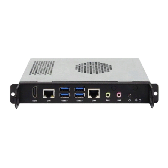
Page 11: Overview
Screw Holes (for the optional docking kit) (From left to right: Line-Out, Mic-In) HDMI Port Antenna Holes GbE LAN Port Power Button LED Indicators USB 3.0 (From left to right: for power, for HDD) RJ50 COM RS-232 Port IOPS-602 User Manual... -
Page 12: Dimensions
General Information 1.7 Dimensions Unit: mm IOPS-602 User Manual... -
Page 13: Chapter 2 Hardware Configuration
Chapter 2 Hardware Configuration This section contains general information about: • Installations • Jumper and connectors... -
Page 14: Installations
To remove a module, use your fingers to press the clips outwards until the module pops up. Grab the module gently and pull it out of the slot. IOPS-602 User Manual... -
Page 15: Cards Installation
1. Fasten the hex nut and the washer. Then 2. Apply adhesive around here. install the antenna. Info: The diameter of the nut is around 6.35 mm (0.25”-36UNC). IOPS-602 User Manual... -
Page 16: Pin Assignment For Com Rs-232 Port
2.2 Pin Assignment for COM RS-232 Port (RJ50 connector) Signal Name Signal Name DSR (Data set ready) DCD (Data carrier detect) Ground DTR (Data terminal ready) Ground CTS (Clear to send) TX (Transmit) RTS (Request to send) RX (Receive) RI (Ring indicator) IOPS-602 User Manual... -
Page 17: Setting The Jumpers
1 2 3 When two pins of a jumper are encased in a jumper cap, this jumper is closed, i.e. turned On. When a jumper cap is removed from two jumper pins, this jumper is open, i.e. turned Off. IOPS-602 User Manual... -
Page 18: Jumper & Connector Locations On Motherboard
Hardware Configuration 2.4 Jumper & Connector Locations on Motherboard Motherboard: OPS602 OPS602 – top view IOPS-602 User Manual... - Page 19 OPS602 – bottom view IOPS-602 User Manual...
-
Page 20: Jumper & Connectors Quick Reference
CN7, CN8 DDR4 SO-DIMM Slot J3, J6 M.2 E2230 Slot M.2 M2280 Slot LED1 (for power), LED Indicator LED2 (for HDD) Factory Use Only JP2, J1, J5 [1]: Refer to 2.2 Pin Assignment for COM RS-232 Port. IOPS-602 User Manual... -
Page 21: Clearing Cmos Data (Jp3)
2.5.1 Clearing CMOS Data (JP3) Function Pin closed Illustration Normal (default) Clear CMOS 2.5.2 Clearing ME Register (JP4) Function Pin closed Illustration Normal (default) Clear CMOS IOPS-602 User Manual... -
Page 22: Cpu Fan Power Connector (Cpu_Fan1)
Hardware Configuration 2.5.3 CPU Fan Power Connector (CPU_FAN1) Signal Name Signal Name Ground Rotation detection +12V 2.5.4 Battery Connector (J4) Signal Name Signal Name Power Ground IOPS-602 User Manual... -
Page 23: Chapter 3 Driver Installation
Chapter 3 Driver Installation The information provided in this chapter includes: • ® Intel Chipset Software Installation Utility • ® Intel HD Graphics Drivers • HD Audio Drivers • LAN Network Drivers • ® Intel Management Engine Components Drivers... -
Page 24: Introduction
INF files for Plug & Play function for the chipset components. Follow the instructions below to complete the installation. 1. Run the Setup.exe file. ® 2. When the Welcome screen to the Intel Chipset Device Software appears, click Next to continue. IOPS-602 User Manual... - Page 25 3. Accept the license agreement and proceed with the installation process. 4. On the Readme File Information screen, click Install. 5. Installation is now complete. Restart the system for changes to take effect. IOPS-602 User Manual...
-
Page 26: Intel Graphics Driver Installation
3. Click Yes to agree with the license agreement and continue the installation. 4. On the Readme File Information and Setup Progress screen, click Next until the installation starts. 5. Installation is now complete. Restart the system for changes to take effect. IOPS-602 User Manual... -
Page 27: Hd Audio Driver Installation
1. Run the Setup.exe file for the installation wizard to start. 2. On the Welcome screen of the InstallShield Wizard, click Next to start installing the audio driver on your system. 3. Installation is now complete. Restart the system for changes to take effect. IOPS-602 User Manual... -
Page 28: Lan Driver Installation
3. Accept the license agreement and click Next. 4. On the Setup Options screen, tick the checkbox to select the desired driver(s) and click Next. 5. Click Install. 6. Installation is now complete. Restart the system for changes to take effect. IOPS-602 User Manual... -
Page 29: Intel Management Engine Components Drivers Installation
2. When the Welcome screen appears, click Next. 3. Accept the license agreement and click Next. 4. Assign a desired destination folder and click Next for installation. 5. Installation is now complete. Restart the system for changes to take effect. IOPS-602 User Manual... -
Page 30: Chapter 4 Bios Setup
Chapter 4 BIOS Setup This chapter describes the different settings available in the AMI BIOS that comes with the board. The topics covered in this chapter are as follows: • Main Settings • Advanced Settings • Chipset Settings • Security Settings •... -
Page 31: Introduction
These defaults have been carefully chosen by both AMI and your system manufacturer to provide the absolute maximum performance and reliability. Changing the defaults could make the system unstable and crash in some cases. IOPS-602 User Manual... -
Page 32: Main Settings
BIOS Setup 4.3 Main Settings BIOS Setting Description System Date Sets the date. Use the <Tab> key to switch between the data elements. System Time Set the time. Use the <Tab> key to switch between the data elements. IOPS-602 User Manual... -
Page 33: Advanced Settings
4.4 Advanced Settings This section allows you to configure, improve your system and allows you to set up some system features according to your preference. 4.4.1 CPU Configuration IOPS-602 User Manual... -
Page 34: Power & Performance
CPPC v2 interface to allow for hardware controlled P-states. Turbo Mode Enables / Disables processor Turbo Mode (EMTTM should be enabled too). AUTO means enabled, unless max. turbo ratio is bigger than 16 – SKL A0 W/A. IOPS-602 User Manual... -
Page 35: Pch-Fw Configuration
Enables / Disables the system ability to hibernate (OS/S4 Sleep State). This option may be not effective with some OS. ACPI Sleep State Selects an ACPI sleep state (Suspend Disabled or S3) where the system will enter when the Suspend button is pressed. IOPS-602 User Manual... -
Page 36: F81846 Super Io Configuration
BIOS Setting Description Serial Port Configuration Sets parameters of Serial Ports (COMA). Enables / Disables the serial port and select an optimal setting for the Super IO device. Power Failure Set parameters of Serial Port 1 (COMA). IOPS-602 User Manual... - Page 37 IO = 2F8h; IRQ = 3, 4, 5, 6, 7, 9, 10, 11, 12 • IO = 3E8h; IRQ = 3, 4, 5, 6, 7, 9, 10, 11, 12 • IO = 2E8h; IRQ = 3, 4, 5, 6, 7, 9, 10, 11, 12 IOPS-602 User Manual...
- Page 38 IO = 2F8h; IRQ = 3, 4, 5, 6, 7, 9, 10, 11, 12 • IO = 3E8h; IRQ = 3, 4, 5, 6, 7, 9, 10, 11, 12 • IO = 2E8h; IRQ = 3, 4, 5, 6, 7, 9, 10, 11, 12 IOPS-602 User Manual...
-
Page 39: Hardware Monitor
The values are read-only values as monitored by the system and show the PC health status. CPUShutdown This field enables or disables the Shutdown Temperature Temperature Options: Disabled, 70°C, 75°C, 80°C, 85°C, 90°C, 95°C IOPS-602 User Manual... -
Page 40: Csm Configuration
BIOS Setup 4.4.7 CSM Configuration BIOS Setting Description Network Controls the execution of UEFI and Legacy PXE OpROM. Options: Do not launch, Legacy IOPS-602 User Manual... -
Page 41: Usb Configuration
The maximum time the device will take before it properly reports itself to the Host Controller. “Auto” uses default value for a Root port it is 100ms. But for a Hub port, the delay is taken from Hub descriptor. IOPS-602 User Manual... -
Page 42: Chipset Settings
Shows PCH parameters 4.5.1 PCH-IO Configuration BIOS Setting Description SATA and RST Shows SATA device options settings. Configuration PCH LAN Controller Enables / Disables onboard NIC. Wake on LAN Enable Enables / Disables integrated LAN to wake to system. IOPS-602 User Manual... - Page 43 SATA Controller(s) Enables / Disables SATA devices. SATA Mode Selection Determines how the SATA controller(s) operate. Options: AHCI Mode, Intel RST Premium Serial ATA Ports Enables / Disables Serial Ports. Hot Plug Designates this port as Hot Pluggable. IOPS-602 User Manual...
-
Page 44: Security Settings
BIOS Setup 4.6 Security Settings BIOS Setting Description Administrator Password Sets an administrator password for the setup utility. User Password Sets a user password. IOPS-602 User Manual... -
Page 45: Boot Settings
There no effect for BBS boot options. Boot Mode Select Selects a Boot mode. Boot Option Priorities Sets the system boot order priorities for hard disk, CD/DVD, USB, Network. IOPS-602 User Manual... -
Page 46: Save & Exit Settings
Restores / Loads defaults values for all the setup Restore Defaults options. Save as User Defaults Saves the changes done so far as user defaults. Restores the user defaults to all the setup Restore User Defaults options. IOPS-602 User Manual... -
Page 47: Appendix
Appendix This section provides the mapping addresses of peripheral devices and the sample code of watchdog timer configuration. • I/O Port Address Map • Interrupt Request Lines (IRQ) • Watchdog Timer Configuration... -
Page 48: I/O Port Address Map
0x0000164E-0x0000164F Motherboard resources 0x00000040-0x00000043 System timer 0x00000050-0x00000053 System timer 0x000003F8-0x000003FF Communications Port (COM1) Communications Port (COM2) 0x000002F8-0x000002FF COM2 comes from the optional docking kit. Intel(R) Active Management Technology - 0x0000F0A0-0x0000F0A7 SOL (COM3) 0x00000000-0x00000CF7 PCI Express Root Complex IOPS-602 User Manual... - Page 49 Mobile 6th/7th Generation Intel(R) 0x0000F040-0x0000F05F Processor Family I/O SMBUS - 9D23 0x0000FF00-0x0000FFFE Motherboard resources 0x00000060-0x00000060 Standard PS/2 Keyboard 0x00000064-0x00000064 Standard PS/2 Keyboard 0x0000F090-0x0000F097 Standard SATA AHCI Controller 0x0000F080-0x0000F083 Standard SATA AHCI Controller 0x0000F060-0x0000F07F Standard SATA AHCI Controller IOPS-602 User Manual...
-
Page 50: Interrupt Request Lines (Irq)
IRQ 4294967290 (Microsoft) IRQ 4294967291 Intel(R) HD Graphics 530 IRQ 4294967292 Intel(R) Ethernet Connection (2) I219-V IRQ 4294967293 Standard SATA AHCI Controller IRQ 4294967294 Intel(R) 100 Series/C230 Series Chipset Family PCI Express Root Port #6 - A115 IOPS-602 User Manual... -
Page 51: Watchdog Timer Configuration
Fintek 81846, program abort.\n"); return(1); }//if (SIO == 0) if (argc != 2) printf(" Parameter incorrect!!\n"); return (1); bTime = strtol (argv[1], endptr, 10); printf("System will reset after %d seconds\n", bTime); if (bTime) EnableWDT(bTime); } else DisableWDT(); } return 0; IOPS-602 User Manual... - Page 52 //--------------------------------------------------------------------------- void DisableWDT(void) unsigned char bBuf; Set_F81846_LD(0x07); //switch to logic device 7 bBuf = Get_F81846_Reg(0xFA); bBuf &= ~0x01; Set_F81846_Reg(0xFA, bBuf); //disable WDTO output bBuf = Get_F81846_Reg(0xF5); bBuf &= ~0x20; bBuf |= 0x40; Set_F81846_Reg(0xF5, bBuf); //disable WDT //--------------------------------------------------------------------------- IOPS-602 User Manual...
- Page 53 Init_Finish; } F81846_BASE = 0x00; result = F81846_BASE; Init_Finish: return (result); //--------------------------------------------------------------------------- void Unlock_F81846 (void) outportb(F81846_INDEX_PORT, F81846_UNLOCK); outportb(F81846_INDEX_PORT, F81846_UNLOCK); //--------------------------------------------------------------------------- void Lock_F81846 (void) outportb(F81846_INDEX_PORT, F81846_LOCK); //--------------------------------------------------------------------------- void Set_F81846_LD( unsigned char LD) Unlock_F81846(); outportb(F81846_INDEX_PORT, F81846_REG_LD); outportb(F81846_DATA_PORT, LD); Lock_F81846(); IOPS-602 User Manual...
- Page 54 //--------------------------------------------------------------------------- #defineF81846_INDEX_PORT (F81846_BASE) #defineF81846_DATA_PORT (F81846_BASE+1) //--------------------------------------------------------------------------- #defineF81846_REG_LD 0x07 //--------------------------------------------------------------------------- #define F81846_UNLOCK 0x87 #defineF81846_LOCK 0xAA //--------------------------------------------------------------------------- unsigned int Init_F81846(void); void Set_F81846_LD( unsigned char); void Set_F81846_Reg( unsigned char, unsigned char); unsigned char Get_F81846_Reg( unsigned char); //--------------------------------------------------------------------------- #endif // F81846_H IOPS-602 User Manual...
Need help?
Do you have a question about the IOPS-602 and is the answer not in the manual?
Questions and answers