
Related Manuals for LEYBOLD Oerlikon EcoDry M 15


Summary of Contents for LEYBOLD Oerlikon EcoDry M 15
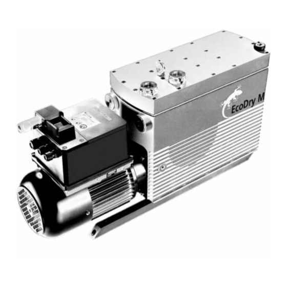
- Page 1 LEYBOLD VACUUM Vacuum Solutions Service Application Support GA 01.703/5.02 EcoDry - M with FC Motor Oil-free Vacuum Pumps EcoDry M 15 130 005 EcoDry M 20 130 015 EcoDry M 30 130 033 Operating Instructions...
-
Page 2: Table Of Contents
Contents Contents Important Safety Considerations ..4 Introduction ......6 Principles of Operation ....6 1.1.1 Stages of Compression . - Page 3 Pumps received without a Declaration of Conta- installation work and the operators res- mination must be returned by Leybold back to the sen- ponsible before beginning with any work der. on the EcoDry.
-
Page 4: Important Safety Considerations
IMPORTANT SAFETY CONSIDERATIONS The Leybold EcoDry M, oil-free vacuum pump is designed for safe and efficient operation when used properly and in accordance with this manual. It is the responsibility of the user to carefully read and strictly observe all safety precau- tions described in this section and throughout the manual. - Page 5 • Do not use the pump for applications that produce abrasive or adhesive powders or condensable vapours that can leave adhesive or high viscosity deposits. Please contact Leybold Sales or Service to select a suitable separator. Also please contact Leybold Sales or Service when planning to pump vapours other than water vapour.
-
Page 6: Introduction
Introduction 1 Introduction EcoDry M pump provides a clean, absolutely oil-free To avoid internal leakage reducing the pump perform- means of evacuation. The gas compression stages ance, the cylinder and piston are manufactured to very close tolerances, leaving almost no gap between them. achieve pressures as low as 5.5·10 mbar (for M 15 / M 30) and 8·10... -
Page 7: Specifications
Specifications 1.2 Specifications EcoDry M 15 EcoDry M 20 EcoDry M 30 Number of cylinders Number of pumping stages Max. pumping speed - at 750 rpm · h - at 1000 rpm · h - at 1200 rpm · h 5.5 ·... - Page 8 Specifications Fig. 1 Dimensional drawing for EcoDry M 15 / 20 GA 01.703/5.02 - 03/03...
- Page 9 Specifications Fig. 1a Dimensional drawing EcoDry M 30 GA 01.703/5.02 - 03/03...
- Page 10 Specifications Pumping speed - Ecodry M15 with world motor Saugvermšgen - Ecodry M15 mit Weltmotor 230 V - 50 Hz - M 15 with silencer, without gas ballast 230 V - 50 Hz - M15 mit SchalldŠmpfer ohne Gasballast Converter pre-set to 750 rpm - 1000 rpm - 1200 rpm Vorgabe Umrichter : 750 U/min - 1000 U/min - 1200 U/min Saugvermšgen [m^3/h] Saugvermšgen-1200 U/min.
-
Page 11: Installation And Operation
2.1 Unpacking the Pump 2.1.3 Inspecting the Pump Inspect the pump for damage. Leybold Vacuum inspects each EcoDry M pump before shipping and packs each pump carefully to avoid dama- If damaged: ge from improper handling. -
Page 12: Supplied Equipment
Installation and Operation 2.1.4 Supplied Equipment 2.2.1 Suggested Installation Procedure The EcoDry M is supplied with the following basic items: Caution The EcoDry M must only be operated in such orientations where the axis of the • Pump with motor pump (crankshaft) runs horizontally. -
Page 13: Connection To The System
Installation and Operation Warning 2.2.2 Connection to the System Make sure that the gas flow at the exhaust Please note the safety information given on port is not blocked or restricted in any way. page 4 and the subsequent pages. If the exhaust gases must be contained or Warning collected, do not allow the exhaust line to... -
Page 14: Opening The Junction Box
Installation and Operation Note The pump complies with NRTL require- 2.3.3 Mains Connection ments. For this reason the system must not be modified without having consulted LV It needs to be ensured that the mains is suf- first. In the case of modifications, the pump ficiently rated to provide the voltage and will no longer comply with NRTL require- power as specified on the name plate. - Page 15 Installation and Operation 3 way terminal strip Socket for the mains plug 9 way terminal strip Cable feedthrough for the control connections Cable feedthrough for the mains cord Removing the 4 hex. socket screw at the junction box Opened junction box Fig.
- Page 16 Installation and Operation LC display START key STOP key ENTER key Fig. 5 Operating panel of the frequency converter Key to Fig. 6 1 Ready / control via serial protocol 2 Accelerating 3 4 x 7 segment display 4 Setpoint speed 5 Actual speed 6 Volt, amps, hours 7 Overspeed...
-
Page 17: Switching On
Installation and Operation 2.4 Switching On 2.4.2.1 Start and Operating Menu As soon as the pump is connected to the mains power, the start and operating menu is invoked automatically. 2.4.1 Operating Panel and LC Display Depending on the currently selected menu, different fun- Function of the keys ctions are assigned to the keys of the operating panel (Fig. - Page 18 Installation and Operation 2.4.2.2 Display Setpiont Menu Keep the “Start” key depressed and use the “Enter” key to scroll through the individual menus. With key for ”A1” Function of the keys Select operating mode ”S” ”S” = Switch mode continue with Fixed speeds: ”0”...
- Page 19 Installation and Operation 2.4.2.3 Speed Setting (Submenu 1) Keep the “START” key depressed again and confirm by pressing “ENTER”. The setpiont menu is selected by operating the “Start” key and the “Enter” key simultaneously. With the “START” key or the “STOP” key change the speed and then confirm by pressing the “ENTER”...
- Page 20 Installation and Operation 2.4.2.4 Voltage / Current Display (Submenu 2) Keep the "START" key depressed and confirm by pres- sing the "ENTER" key three times. Function of the keys Toggle between voltage and current readout Toggle between voltage and current readout Display Back to main menu: GA 01.703/5.02 - 03/03...
- Page 21 Installation and Operation 2.4.2.5 Operating Hours (Submenu 3) Keep the "START" key depressed and confirm by pres- sing the "ENTER" key four times. Back to speed select Function of the keys For adjusting the speed-specific number of operating hours Change speed: To read the number of operating hours Back to main menu...
- Page 22 Installation and Operation 2.4.2.6 Error code Display (Special Menu) This menu can not (!) be selected manually. This menu will be displayed in the case of a fault. Not used Not used Not used GA 01.703/5.02 - 03/03...
-
Page 23: Operating The Pump
Operating the Pump 3 Operating the Pump After having put the cover back on to the junction box, Error code BIT Description the ECO drive may be started. E001 Short circuit affecting current inverter E002 Overvoltage in intermediate circuit E004 Mains voltage is too low 3.1 Error Messages during E008... -
Page 24: Rs 485 Parameter List
Operating the Pump 3.3 RS 485 Parameter List PKE Nos. 0-26 are process data which can be read through the parameter channel of the USS protocol. PKE Nos. 64-83 are data from the EEPROM. Designation EEPROM Resolution Description / address Solution Status/Cmd Read command... - Page 25 Operating the Pump Designation EEPROM Resolution Description address Solution ee_motor_temp 0x44 Error counter motor overtemperature ee_offset 0x45 Error counter current offset ee_innen_temp 0x46 Error counter internal temperature ee_ueberstrom 0x47 Error counter motor overcurrent * t sum ee_i2t 0x48 Error counter I ee_motor_ptc 0x49 Error counter motor PTC...
-
Page 26: Application Notes
In case of any questions produce abrasive or adhesive substances in this matter do not hesitate to get in touch or condensable vapours that can leave with Leybold Vacuum. adhesive or high viscosity deposits. Also the formation of thicker deposits Generally the following applies: should be avoided since these too may form •... -
Page 27: Repair, Maintenance And Service
EcoDry M, any maintenan- ce regarding operating agents and consumption is not required. Leybold Vacuum recommends to have the sealing collars replaced once per year (further information upon request). When returning equipment to our Service please fill in completely the “Declaration of Contamination”... -
Page 28: Troubleshooting
Troubleshooting 6 Troubleshooting Fault Possible cause Remedy Repair Pump does not Faulty wiring. Check the wiring and repair it. Electrician start up. Motor defective. Exchange the motor. Service Pump has seized. Repair the pump. Service Pump does not Method of measurement or measuring instrument not suitable. Use the right method of measurement or measuring instrument. -
Page 29: Ec Declaration Of Conformity
CE Declaration of Conformity We – LEYBOLD VACUUM GmbH – herewith declare The products comply with the following guidelines that the products defined below meet the basic require- • EC Directive on Machinery (98/37/EG) ments regarding safety and health of the relevant EC directives by design, type and the versions which are •... - Page 30 GA 01.703/5.02 - 03/03...
Need help?
Do you have a question about the Oerlikon EcoDry M 15 and is the answer not in the manual?
Questions and answers