
Related Manuals for Siemens FC18


Summary of Contents for Siemens FC18
- Page 1 FC18 Controller Operating manual Building Technologies Fire Safety & Security Products...
-
Page 2: Table Of Contents
Operating Manual of FC18 Controller TABLE OF CONTENTS CHAPTER 1 SYSTEM OVERVIEW ················································································································ 3 FEATURES ······································································································································· 3 TECHNICAL DATA ····························································································································· 4 DIMENSIONS···································································································································· 5 COMPATIBLE EQUIPMENT LIST ··········································································································· 5 SYSTEM STRUCTURE ······················································································································· 6 CHAPTER 2 INSTALLATION ······················································································································· 8 INSTALLATION ·································································································································· 8 CONNECTION DIAGRAM ····················································································································... - Page 3 Operating Manual of FC18 Controller 31. HOW TO REPLACE DEVICE ·············································································································· 48 32. HOW TO UPGRADE TO FC1840 ········································································································· 49 33. HOW TO CHANGE LANGUAGE ·········································································································· 50 34. HOW TO QUERY THE INFORMATION OF OTHER EVENTS ······································································ 51 CHAPTER 4 MAINTENANCE ······················································································································ 52 DAILY EXAMINATION ·······················································································································...
-
Page 4: Chapter 1 System Overview
Efficient group programming according to different using. FC1820 controller can connect up to 252 points, FC1840(C) controller can connect up to 504 points. Network bus (FC18-BUS), the max. distance is 1000m ( ). Up to the twist wiring capacity is 1.0 to 1.5 mm 32 controllers can be networked together with FC1820 and FC1840(C). -
Page 5: Technical Data
Max. history records 10000 Max. distance between controllers within FC18-BUS 1,000 m Max. No. of controllers connected within FC18-BUS Max. distance between a controller and a FRT within FR18-BUS 1,000 m Max. No of FRT connected to a controller Auto-mapping function... -
Page 6: Dimensions
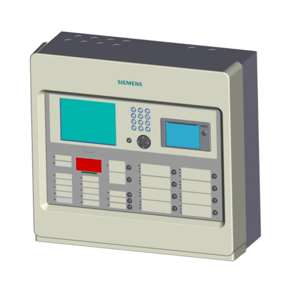
Operating Manual of FC18 Controller DIMENSIONS Fig. 1-1 FC18 Appearance Fig. 1-2 FC18 Dimensions (mm) COMPATIBLE LIST Type Description FDT181 Addressable heat detector FDO181 Addressable smoke detector FDM181 Addressable manual call point FDCI181-2 Addressable input module FDCIO181-2 Addressable input/output module... -
Page 7: System Structure
Operating Manual of FC18 Controller SYSTEM STRUCTURE Up to 32 FC1820/40(C) controllers can be networked together. Any controller can be set as master controller to supervise devices connected with its slave controller and its own. Fig. 1-3 System structure Page: 6/63... - Page 8 Operating Manual of FC18 Controller Pinter Keyboard 1 Terminal board Power supply Main board Line card 2 Line card 1 LED screen CPU board Battery Keyboard 2 Interlocking panel Fig. 1-4 Internal structure Page: 7/63...
-
Page 9: Chapter 2 Installation
Operating Manual of FC18 Controller CHAPTER 2 INSTALLATION INSTALLATION Fig. 2-1 Dimensions (mm) Installation must comply with the local regulation! 1. Ensure the wall is dry, clean, flat and firm in which the controller is installed. 2. Chose a proper installation location to make sure the front door can be opened smoothly. -
Page 10: Connection Diagram
Fig. 2-4 FRT/Mimic driver connection diagram Note: Ensure positive and negative connections are properly in place; FC18-BUS is polarity sensitive. Connect a 120Ω resistor as monitoring resistor. It must be connected to the end of the line. ( It can be set by the two-digit Dip-switch on the main board, see “Dip-switch connection configuration”... -
Page 11: Dip-Switch
Each controller/interlocking panel has an eight-digit Dip-switch for address setting. Each Dip-switch can set address 1-32 within its first 6 digits. DIP switches FC18-BUS address Idle The controller has a two-digit Dip-switch for setting terminal resistor of FC18-BUS or FR18-BUS. On:FC18-BUS terminal selected; Off:not selected On:FR18-BUS terminal selected; Off:not selected Page: 10/63... -
Page 12: Power Supply
Operating Manual of FC18 Controller Power Supply Stable and reliable DC output Auto switch between main power and battery Alternative AC power switch Charge and protect battery Monitor main power, battery, trouble status Auto recoverable current protection circuit for overload and short circuit... - Page 13 Operating Manual of FC18 Controller Connect to port “Pwr Connect to Connect to port Status” on main unit battery ” PS” on main unit Connect external AC input Fig. 2-10 Wire connection Specification of power supply Input voltage 110/220 VAC...
-
Page 14: Chapter 3 Operation
Operating Manual of FC18 Controller CHAPTER 3 OPERATION 1. INTERFACE Fig. 3-1 Operation panel ① LCD The LCD backlight automatically turns off within the preset time in the idle mode; the preset time can be adjusted in the parameter setting. Press any key will turn on the LCD again. - Page 15 Operating Manual of FC18 Controller System trouble: On when system hardware/software is faulty. ¹ ¹ Trouble: On when trouble occurs; Off when trouble is resolved. Activation: On when some equipment (such as output module or main board output port) is activated; Off when ¹...
- Page 16 Operating Manual of FC18 Controller until master is reset. ⑤ Interlocking panel The interlocking panel has 8 output channels. Each channel has indicators to indicate trouble, activation and confirmation status. Each channel can be controlled manually with Activation/Deactivation button. Only level 2&3 user can access.
-
Page 17: Lcd Window
② ③ Fig. 3-2 Display screen FC18 controller has 3 windows which are menu window (1), browser window (2) and statistics window (3). ① Menu window: ¹ Display different operation menus according to different user levels. Items for Level 3 are shown as follows. - Page 18 Operating Manual of FC18 Controller ② Browser window: ¹ Display real-time events: fire alarm, activation & confirmation, trouble, supervision, disable, test and walk-test. ¹ Display node tree. ¹ Priority of display: fire alarm→ activation & confirmation→ supervision→ disable→ trouble→ test/walk-test→ normal.
-
Page 19: User Level
Operating Manual of FC18 Controller 3. USER LEVEL FC18 has 3 user levels. User level is displayed at the lower right corner of the screen (Fig. 3-2) Users of different levels have their own matching privileges and interfaces. Table 3-1 user privilege list... -
Page 20: Login
Operating Manual of FC18 Controller Login Press “Menu” to browse the main menu. Display main menu. Press”→” to select “Login”, and then press “OK”. Password entry window pops out. Fig. 3-3 Enter the password for Level2/3 and press “OK”. Login as a Level 2/3 user if the password entered is correct. -
Page 21: Status Types
Operating Manual of FC18 Controller STATUS TYPES FC18 controller contains 8 status types: normal, fire alarm/activation, trouble, supervision, disable, test/walk-test and locate. Normal: Event Brow Help Login l Main power supply indicator on l Auto/Manual indicator on System Normal SIEMENS Building... - Page 22 Operating Manual of FC18 Controller Activation status: Activation Activation indicator on (flashing when there is no confirmation) 0001 Activation 2008-08-08 10:10:13 Output 1 / 01.005.008 LCD shown as the figure Acknowledge/Silence indicator flashing Buzzer ringing Fig. 4-5 Confirmation status: Confirmation...
-
Page 23: Fire Alarm Event Handling
Operating Manual of FC18 Controller FIRE ALARM EVENT HANDLING Fire alarm status: Fire alarm indicator turns on Fire event with customer information shown in the LCD as the figure Acknowledge/Silence indicator flashing NAC activation indicator turns on Buzzer turns on... -
Page 24: Trouble Event Handling
Go to the site to trouble-shoot. The trouble indicator turns off when problems are solved. If you cannot solve the problem, please call local Siemens service center. Note: When a trouble occurs together with another event of higher priority, trouble event cannot be displayed automatically. -
Page 25: Supervision Event Handling
Operating Manual of FC18 Controller SUPERVISION EVENT HANDLING Supervision status: Supervision indicator on Supervision events are shown on the LCD as the figure Acknowledge/Silence indicator flashing Buzzer turns on How to handle: Press “Acknowledge/Silence” to silence the buzzer: Under Level 1 interface, a login interface pops out automatically. Enter Fig.7-1... -
Page 26: Activation/Confirmation Event Handling
Operating Manual of FC18 Controller ACTIVATION/CONFIRMATION EVENT HANDLING Activation status: Activation indicator on (flashing if there is no confirmation) Confirmation indicator on (only if there is confirmation signal) Activation events are shown on the LCD as the figure Acknowledge/Silence indicator flashing... -
Page 27: Real-Time Query
Operating Manual of FC18 Controller REAL-TIME QUERY FC18 fire alarm controller (interlocking) contains ten types of real-time events: Table 3-2 Types of real-time events Priority Fire alarm/activation Supervision Disable Trouble Test Walk-test Locate Unconfigure equipment Unknown equipment Inconsistent equipment Exchange equipment Unconfigure equipment: Equipments not on the engineering document list. -
Page 28: How To Query Equipment Property
Operating Manual of FC18 Controller 10. HOW TO QUERY EQUIPMENT PROPERTY Steps: Trouble Select a station, a line or a point and press “→” to pop out a shortcut menu 0002 COMM trouble 2008-08-08 10:10:10 Interlocking Line / 01.005 (Fig. 10-1), then select “Property” and press “OK” to pop out a property... -
Page 29: How To Query History
Operating Manual of FC18 Controller 11. HOW TO QUERY HISTORY FC18 fire alarm controller (interlocking) contains 11 types of history records which are fire alarm, trouble, supervision, activation/confirmation, disable, test and walk-test, unconfigure equipment, unknown equipment, inconsistent equipment, exchange equipment. The first six types support advanced query. -
Page 30: How To Disable/Enable
Operating Manual of FC18 Controller 12. HOW TO DISABLE/ENABLE Function: The controller should be disabled when the house is being decorated or there are equipment damages or failure. It should be resumed to normal state as soon as the decorating work or equipment repair is finished. -
Page 31: How To Activate/Deactivate The Controller
Operating Manual of FC18 Controller 13. HOW TO ACTIVATE/DEACTIVATE THE CONTROLLER Function: Through controller, manually activation/deactivation mainboard output, output module, interlocking panel output and NAC devices etc. Steps to activation: Press “Menu” to browse the main menu (Fig. 13-1). Main menu displayed. -
Page 32: How To Test/Walk-Test
Operating Manual of FC18 Controller 14. HOW TO TEST/WALK-TEST Function: To test whether the alarm device is in normal status. Under test/walk-test mode, an alarm will be triggered when there is an alarm event while the interlocking equipment will not be activated. Make sure the controller is back to normal after the test. -
Page 33: How To Locate/Stop Locating
Operating Manual of FC18 Controller 15. HOW TO LOCATE/STOP LOCATING Function: To locate equipment. Steps to locate: Press “Menu” to browse the main menu (Fig. 15-1) Main menu displayed. Press “→” to select “Brow” submenu (Fig. 15-2). Press “↓” to select “All”, then press “OK”... -
Page 34: How To Adjust Buzzer Level
Operating Manual of FC18 Controller 16. HOW TO ADJUST BUZZER LEVEL Function: Turn up or down the buzzer between level 0-7. Level 0 is mute mode. Steps: Press “Menu” to browse the main menu (Fig. 16-1) Main menu displayed. Fig.16-1 Press “→”... -
Page 35: How To Set Login Time
Operating Manual of FC18 Controller 17. HOW TO SET LOGIN TIME Function: Under 2/3 level, if there is no operation in preset login time, controller will automatically log out to 1level. Setting range: 1-60 minutes. Steps: Press “Menu” to browse the main menu (Fig. 17-1) Main menu displayed. -
Page 36: How To Set Walk-Test Time
Operating Manual of FC18 Controller 18. HOW TO SET WALK-TEST TIME Function: Controller being tested will restore to normal status automatically after the preset walk-test time. Setting range: 1-60 min. Steps: Press “Menu” to browse the main menu (Fig. 18-1) Main menu displayed. -
Page 37: How To Set Lcd Closing Time
Operating Manual of FC18 Controller 19. HOW TO SET LCD CLOSING TIME Function: LCD turns off its back light if there is no operation or event during the preset LCD closing time. Press any key to turn on the back light. Setting range: 1-60 min. -
Page 38: How To Set Time
Operating Manual of FC18 Controller 20. HOW TO SET TIME Function: To set system time. Steps: Press “Menu” to browse the main menu (Fig. 20-1) Main menu displayed. Fig.20-1 Press “→” to pop out the "Tool" submenu (Fig.20-2). Select “Set Time" and press “OK”... -
Page 39: How To Check System
Operating Manual of FC18 Controller 21. HOW TO CHECK SYSTEM Function: To check whether the LCD, indicators, printer and the buzzer are in normal state. Steps: Press “Menu” to browse the main menu (Fig. 21-1) Main menu displayed. Fig.21-1 Press “→” to pop out the "Tool" submenu (Fig.21-2). Press "↓" to select “Check System"... -
Page 40: How To Save Configure
Operating Manual of FC18 Controller 22. HOW TO SAVE CONFIGURE Function: Save changes permanently, otherwise the changes will be lost when the system is restarted. Steps: Press “Menu” to browse the main menu (Fig. 22-1) Main menu displayed. Fig.22-1 Press “→” to pop out the "Conf" submenu (Fig.22-2). Press "↓" to select “Save Configure"... -
Page 41: How To Edit Parameter
Operating Manual of FC18 Controller 23. HOW TO EDIT PARAMETER Function: To modify parameters in system. See Appendix table 1 for details. Steps: Press “Menu” to browse the main menu (Fig. 23-1) Main menu displayed. Fig.23-1 Press “→” to select “Brow” submenu (Fig. 23-2). Press “↓” to select the item which contains the equipment whose parameters need to be modified, and then press “OK”. -
Page 42: How To Create/View Logic
Operating Manual of FC18 Controller 24. HOW TO CREATE/VIEW LOGIC Function: To create/view logic among detection group, supervision group and control output group. Steps: Press “Menu” to browse the main menu (Fig. 24-1) Main menu displayed. Press “→” to select “Brow” submenu (Fig. 24-2). Select "All" and then press “OK”. -
Page 43: How To Edit/Delete Logic
Operating Manual of FC18 Controller 25. HOW TO EDIT/DELETE LOGIC Function: To modify or delete logic. Steps: Press “Menu” to browse the main menu (Fig. 25-1) Main menu displayed. Fig.25-1 Press “→” to select “Browse” submenu (Fig. 25-2). Select "All" and then press “OK”. -
Page 44: How To Assign Group/ Frt
Operating Manual of FC18 Controller 26. HOW TO ASSIGN GROUP/ FRT Function: It's more convenient to edit logic with the concept of "Group". There are four groups in the system: detection group, control output group, supervision group and FRT group. See Appendix table 3 for details. -
Page 45: How To Get Help
Operating Manual of FC18 Controller 27. HOW TO GET HELP Function: To show the company name, system edition, product series No, download time of configuration file and modification time. Steps: Press “Menu” to browse the main menu (Fig. 27-1) Main menu displayed. -
Page 46: How To Operate Interlocking Panel
Operating Manual of FC18 Controller 28. HOW TO OPERATE INTERLOCKING PANEL Function: The interlocking penal has 8 channels of input/output. Each of them has indicators of trouble, activation and confirmation to indicate its state, as well as activation/deactivation key for manual control. -
Page 47: How To Open/Close A Printer
Operating Manual of FC18 Controller 29. HOW TO OPEN/CLOSE A PRINTER Function: When the printer is open, it can print real-time events at any time and print history records if needed (see "History Query"); when it is off, it cannot print anything. - Page 48 Operating Manual of FC18 Controller Operations of printer: There are two indicators and two keys. Indicators are under the transparent key. Indicator: Green indicator indicates electrifying state of printer; red indicator indicates working state of printer (online/offline). Green Normal power supply...
-
Page 49: How To Replace Device
Operating Manual of FC18 Controller 30. HOW TO REPLACE DEVICE Function: To copy the configuration information to the new equipment when the old one is replaced. Steps: Press “Menu” to browse the main menu (Fig. 30-1) Main menu displayed. Fig.30-1 Press “→”... -
Page 50: How To Upgrade To Fc1840
Operating Manual of FC18 Controller 31. HOW TO UPGRADE TO FC1840 Function: The FC18 wall-mounted controller has two types: the FC1820 and the FC1840. FC1820 can be upgraded to FC 1840 through adding a loop card and conducting the following operations. -
Page 51: How To Change Language
Operating Manual of FC18 Controller 32. HOW TO CHANGE LANGUAGE Function: The system provides four kinds of language: English, Taiwan, Hongkong, and Portuguese. Apply languages as needed. Steps: Press “Menu” to browse the main menu (Fig. 32-1). Main menu displayed. -
Page 52: How To Query The Information Of Other Events
Operating Manual of FC18 Controller 33. HOW TO QUERY THE INFORMATION OF OTHER EVENTS Function: Other events include: Test, Walktest, Locate, Unconfigure, Unknown, Inconsistent, and Exchage. Through this function, can check the qty for each event. Step: Press “Menu” to browse the main menu (Fig. 33-1). -
Page 53: Chapter 4 Maintenance
Operating Manual of FC18 Controller CHAPTER 4 MAINTENANCE 1. DAILY EXAMINATION Operator on duty should examine controllers every day and record status. If there is fire alarm, error or other abnormal status, please follow “Emergency Failure Guideline”; when controller gets normal again, the event should be recorded. - Page 54 Operating Manual of FC18 Controller Failure phenomenon Cause analysis Solving Method Power trouble; Change the software Engineer software configuration not in line configuration; with actual equipment; Change the address Address not set for circuit card or not in line configuration;...
-
Page 55: Appendix 1 Parameter List
Operating Manual of FC18 Controller APPENDIX 1 PARAMETER LIST Equipment type Editable item Parameter description System Text System name Station Text Controller name - FC1820 Login time Under 2nd/3rd level, if there is no operation in preset login time, controller... - Page 56 Operating Manual of FC18 Controller Fire alarm input Text Equipment location/function description (interlocking panel and main board input) Output without confirmation Text Equipment location/function description (FDCIO181) Inversion Option 1: Normal (Active When NO is closed) (default) Option 2: Inverting (Active when NC is open)
- Page 57 Operating Manual of FC18 Controller Output style Switched voltage control output. (Default) Option 1: Dry contact Option 2: Output with confirmation Text Equipment location description (interlocking panel and main Supervision time In preset supervision time, if there is no confirmation signal received, board output) system defines it as activation without confirmation.
-
Page 58: Appendix 2 Operable Item List
Operating Manual of FC18 Controller APPENDIX 2 OPERABLE ITEM LIST Controller: Operational item Controller Auto/Manual* Set time System Check FC1820 √ √ √ √ √ √ FC1840 [ * ] Auto/Manual can only be switched through buttons on controllers. Line:... - Page 59 Operating Manual of FC18 Controller Group: Group Operational item Activation/ Disable/ Deactivation Enable Control group √ ------- Detection group ------- ------- Supervision group ------- -------- FRT group ------- √ “Ö“ indicates operational; “----” indicates not operational. Page: 58/63...
-
Page 60: Appendix 3 Equipment Grouping Table
Operating Manual of FC18 Controller APPENDIX 3 EQUIPMENT GROUPING TABLE Control Detecting Supervision Fire display Equipment type output group group panel group group FDO181 Smoke detector √ √ FDT181 Heat detector √ √ FDM181 Manual Call Point √ √ FDHM181 Hydrant Manual Call Point √... -
Page 61: Appendix 4 Rules For Logic Expression
Operating Manual of FC18 Controller APPENDIX 4 RULES FOR LOGIC EXPRESSION Logic expression: 01.0001.07+01.0002.07+01.0003.07=01.0004.10 Input Output ① Group No.: xx.xxxx first two numbers express controller No.; last four numbers express group code. ② Status code:xx express the status in the logic 01:Alarm... - Page 62 Operating Manual of FC18 Controller ● “@N”: Union alarm in a group, 2≤N≤ total device amount; Example: 01.0001@2=01.0004; indicates that any 2 devices in group 01.0001 alarm can activate group 01.0004. Remark: when adding /deleting device in a group, the logic expression needs to be verified.
-
Page 63: Appendix 5 Input Method
Operating Manual of FC18 Controller APPENDIX 5 INPUT METHOD Letter/Number input: Press down letter/number key, then input content will switch between number and letter. When switched to needed content, relieve the key to complete the input of needed letter/number. Special character input: Press down number key (1), then input content will switch among '1', '.', '+',... -
Page 64: Appendix 6 "Sticker Method"Easy For Commissioning
Operating Manual of FC18 Controller APPENDIX 6 “STICKER METHOD”EASY FOR COMMISSIONING In FD18 system, there is an exclusive ID number on each spot component. Engineer debug staffs can tear it down when installing, and fix to the equipment position in engineering drawings, so that after installation of all components, engineer file configuration can be made. - Page 65 © 2012 Copyright by Beijing Siemens Cerberus Electronics Limited No.1,Fengzhidonglu, Xibeiwang, HaiDian District, Beijing Siemens Cerberus Electronics Ltd. Beijing, 100094, China Data and design subject to change without notice. Tel: +10 6476 8806 Fax: +10 6476 8899 Document no. A6V10322968_e_en_--...
Need help?
Do you have a question about the FC18 and is the answer not in the manual?
Questions and answers
How to delete address IM on panel
To delete an address (IM) on the Siemens FC18 panel, follow these steps:
1. Press “Menu” to open the main menu.
2. Press “→” to select the “Brow” submenu.
3. Select “All” and press “OK” to display the tree diagram.
4. Use “↓” / “↑” to find and select the device (IM address) you want to delete.
5. Press “→” to open the shortcut menu.
6. Use “↓” to select the option related to deleting or editing the device.
7. If deletion is confirmed, a dialog box may appear asking for confirmation.
8. Press “OK” to delete permanently or “CANCEL” to abort.
Note: Deletion operations may be temporary unless saved. Use “Menu” > “Confirm” > “OK” to save changes.
This answer is automatically generated