Table of Contents
Advertisement
Quick Links
REQUIRED TOOLS
AND MATERIALS:
• 2 Capable Adults
• Tape Measure
• Step Ladder - 8ft.
(2.4 m)
• Carpenter's Level
• (2 each) Wrenches
and/or Socket Wrenches
and Sockets (Deep-Well
Sockets are
Recommended).
1/2"
9/16"
AND/OR
1/2"
9/16"
3/4"
• Extension is
Recommended.
OPTIONAL TOOLS
AND MATERIALS:
• Large and Small
Adjustable Wrenches
© COPYRIGHT 2006 by SPALDING
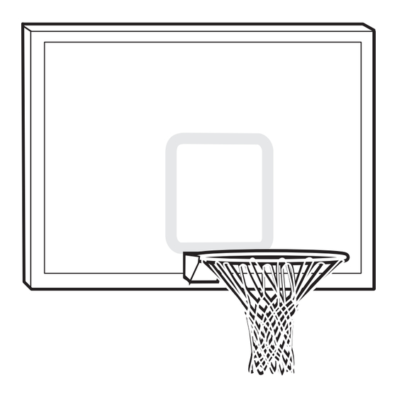
Backboard and Rim
Owners Manual
• N53 W24700 South Corporate Circle • Sussex, WI 53089 • U.S.A.
3/4"
This manual, accompanied by sales receipt, should be saved and kept on hand as a
convenient reference, as it contains important information about your model.
Customer Service Center
Adult Assembly Required.
WARNING!
READ AND UNDERSTAND
OPERATOR'S MANUAL
BEFORE USING THIS UNIT.
FAILURE TO FOLLOW
OPERATING INSTRUCTIONS
COULD RESULT IN INJURY
OR DAMAGE TO PROPERTY.
Toll-Free Customer Service Number for U.S: 1-800-558-5234,
For Canada: 1-800-284-8339,
For Europe: 00 800 555 85234 (Sweden: 009 555 85234),
For Australia: 1-800-632 7921
Internet Address: http://www.huffysports.com
1
Write Model Number
From Box Here:
05/06 ID#
M7900412
Advertisement
Table of Contents

Summary of Contents for SPALDING M7900412
-
Page 1: Owners Manual
OR DAMAGE TO PROPERTY. Toll-Free Customer Service Number for U.S: 1-800-558-5234, For Canada: 1-800-284-8339, For Europe: 00 800 555 85234 (Sweden: 009 555 85234), For Australia: 1-800-632 7921 Internet Address: http://www.huffysports.com Write Model Number From Box Here: 05/06 ID# M7900412... -
Page 2: Safety Instructions
05/05 PRODUCT REGISTRATION: Please remember to complete your product registration form on- line at: www.huffysports.com/customer_support/product_registration. M7900412 05/06 WARRANTY. Most injuries are caused by misuse and/or not following instructions. Use caution when using this system. website at http://www.smarthoops.com. NOTICE TO ASSEMBLERS inspect for loose small parts. - Page 3 202603 Nylon Washer 202602 Lock Washer 202636 Special Nut, Locking 203795 Special Nut 1 90832901 H-Frame 205457 Foam Tape 204622 Bolt, Hex, 3/8 x 1.75” Long 200580 Bracket, Angle, 1.5” x 1.4” Backboard #12 (2) #20 (2) 05/06 ID# M7900412...
-
Page 4: Hardware Identifier
#24 (2) #25 (2) #26 (2) #10 (2) HARDWARE IDENTIFIER (Not Actual Size) #18 (1) #1 (1) #13 (1) #15 (1) #14 (1) #7 (2) LOGO #28 (1) Item #30 (2) #19 (1) #22 (2) #27 (1) #31 (1) M7900412 05/06... -
Page 5: Tools Required
THAT MAY HAVE OCCURRED DURING SHIPMENT. CRACKS IN THE BACKBOARD COULD RESULT IN SUDDEN BREAKAGE. IF BACKBOARD IS DAMAGED IN ANY WAY PRIOR TO OR AFTER ASSEMBLY, CALL TOLL-FREE NUMBER: U.S. 1-800-558-5234; CANADA: 1-800-284-8339; http://www.huffysports.com WARNING! TOOLS REQUIRED 1/2" 9/16" 3/4" AND/OR 1/2" 9/16" 3/4" 05/06 ID# M7900412... - Page 6 WARNING COULD RESULT IN SERIOUS INJURY AND/OR PROPERTY DAMAGE. If being used with an extension arm attach angled brackets (30) to H-Frame as shown. M7900412 05/06 NOTE: We recommend mounting backboard to a solid material (steel) behind rim area. NOTE:...
- Page 7 Lift backboard upright and insert bolt (20) through board into H-frame (27). Secure using nut (17) as shown. WARNING! TWO CAPABLE ADULTS REQUIRED FOR THIS PROCEDURE. FAILURE TO FOLLOW THIS WARNING COULD RESULT IN SERIOUS INJURY AND/OR PROPERTY DAMAGE. 05/06 ID# M7900412...
- Page 8 Tighten nuts (4) completely. Place a special locking nut (25) approximately half-way up on each carriage bolt (2) as shown. Keep the two special locking nuts (25) at the same level. M7900412 05/06 RIM ASSEMBLY & INSTALLATION NOTE: Perform this step twice...
-
Page 9: Bottom View
Then, insert spacer (10) through back bracket (13), nylon washers (23) and rim assembly (1). BOTTOM VIEW Spacer flush with bracket Line up holes NOTE: Ends of spacer (10) should be flush on both sides of board bracket (13). BOTTOM VIEW Spacer flush with bracket 05/06 ID# M7900412... - Page 10 Install bolt (11) through top holes on bracket (13) using washers (6) and nut (5) as shown. Tighten completely. Attach rim assembly to backboard and support structure by inserting bolts (16) through bottom holes in back bracket (13). Secure with nuts (17) and washers (6). Tighten nuts (17) completely. M7900412 05/06...
- Page 11 (2) as shown. NOTE: Do not over tighten as rim will not flex properly. See leveling instructions (Step 13) to determine how much to tighten nuts (25 and 26). NOTE: COMPLETED ASSEMBLY 05/06 ID# M7900412...
- Page 12 Insert spacer (10) through bottom holes in board bracket (13) and inner bracket (14). Ends of spacer (10) should be flush on both sides of board M7900412 05/06 NOTE: bracket (13). Spacer flush with...
- Page 13 TO LEVEL RIM, TIGHTEN OR LOOSEN THESE NUTS TO ADJUST RIM TENSION , TIGHTEN OR LOOSEN THESE NUTS 202531 Place level on rim (1) and adjust nut (25) until level. Tighten nut (26) to set rim tension for playing. 05/06 ID# M7900412...
-
Page 14: Outside View
(12) as shown (note orientation of cover plate). NOTE: Cover plate (15) will fit INSIDE back bracket. Secure net (18) to rim (1). M7900412 05/06 OUTSIDE VIEW NOTE: Official rim height is 10-0’ (3.05 m) from top of rim to playing surface. 10 ft.


Need help?
Do you have a question about the M7900412 and is the answer not in the manual?
Questions and answers