
Related Manuals for Icop VEX-SOM


Summary of Contents for Icop VEX-SOM
- Page 1 User Manual VEX-SOM DM&P Vortex86EX 400MHz processor with FPU Version 3.0 ICOP Technology Inc.
- Page 2 No part of this manual may be reproduced, copied, translated or transmitted, in whole or in part, in any form or by any means without the prior to written permission of ICOP Technology Inc. ⓒCopyright 2015 ICOP Technology Inc Trademarks Acknowledgement Vortex86EX is the registered trademark of DM&P Electronics Inc.
-
Page 3: Revision History
VEX-SOM User Manual Revision History Revision Date Remark Aug 14, 2014 First release. Sep 9, 2015 New version released Nov. 3, 2016 Add Appendix ICOP Technology Inc. -
Page 4: Table Of Contents
3.2 DC Characteristics ........................16 Programmable I/O Selection ......................17 4.1 Programmable I/O overview ....................17 4.2 Usage of SocCfg Tool......................... 19 Setup the programmable I/O ......................20 5. Software Resources ..........................21 5.1 BIOS ............................. 21 5.2 Software ............................21 ICOP Technology Inc. - Page 5 VEX-SOM User Manual 6 ADC................................. 22 6.1 ADC overview ..........................22 6.2 ADC Characteristic ........................22 6.3 ADC Sample code ........................22 7. Evaluation Board ..........................23 Appendix ..............................24 Warranty ..............................27 ICOP Technology Inc.
-
Page 6: General Information
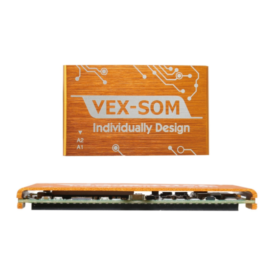
1 General Information General Information 1.1 Overview The VEX-SOM is a 45 x 28 mm, 128 pins, single +5V input, System On mm, 128 pins, single +5V input, System On Module with onboard CPU, DRAM and SPI Flash; also take advantage of Module with onboard CPU, DRAM and SPI Flash;... -
Page 7: Block Diagram
VEX-SOM User Manual 1.2 Block diagram ICOP Technology Inc. -
Page 8: Specifications
USB Device port, version:1.1 port Device Link and Duplex LED for LAN LED build-in Ethernet Keyboard PS/2 Keyboard port Mouse PS/2 Mouse port WDTOUT WatchDog timeout signal Clock output select from CLK OUT 14.318MHz /24MHz /25MHz ISA Clock ICOP Technology Inc. - Page 9 - Windows CE 5.0 , CE 6.0 , Compact 7 Operating System - VxWorks 5.5 & 6.8 Support - QNX 6.3.2 - FreeBSD, OpenBSD and NetBSD. - Other real time OS has 486 supports, for example RTOS-32. ICOP Technology Inc.
-
Page 10: Ordering Information
VEX-SOM Vortex86EX SOM 128 pin CPU Module with 128MB DDR3 Vortex86EX SOM 128 pin CPU Module with 128MB DDR3, VEX-SOM-X -40°C ~+85°C support VEX-SOM Development Board*1 MINIPCIE VGA cable*1 GPIO cable*5 VEX-SOM-DEV Mini PCI VGA Board*1 Mini PCI express to PCI express converter*1... -
Page 11: Hardware Information
VEX-SOM User Manual 2 Hardware Information Hardware Information 2.1 Dimension Optional heat sink with holder Optional heat sink with holder VEX-SOM ICOP Technology Inc. - Page 12 VEX-SOM User Manual Unit: mm ICOP Technology Inc.
-
Page 13: Connectors
Conn Top item number: number: H3N25-232D1BKC002F ICOP item number: number: PH2*32(1.27)-5.3MM Option 2: Vendor: Samtec. Item number: number: FTSH-132-02-F-DV Note: Customer can buy “Option 1” connector from ICOP. The item number is PH2*32(1.27)-5.3MM. For details, please contact ICOP sales. ICOP Technology Inc. -
Page 14: Recommended Layout (For Module)
VEX-SOM User Manual 2.3 Recommended Layout (for module) Please keep the whole area empty between two matching connector on your carrier board. ICOP Technology Inc. -
Page 15: Pin Assignments & Jumper Setting
2.4 Pin Assignments & Jumper Setting 2.4.1 Pin assignment As the image above, there are two rows of connector on VEX-SOM; Pin A1~A64 is on the left and Pin B1~B64 is on the right. Please see the pin assignments on the next page. - Page 16 GP35 PE0_CLK- PCIRST- GP36 GP37 PE0_CLK+ RESET- GP20 GP21 GP22 GP23 LANTX- LANRX- GP24 GP25 LANTX+ LANRX+ GP26 GP27 VBATT VCC1.8_OUT GP80 GP81 GP10 GP11 GP82 GP83 GP12 GP13 GP84 GP85 GP14 GP15 GP86 GP87 GP16 GP17 ICOP Technology Inc.
-
Page 17: Pin Table List
SATA_TX-, SATA_RX-, SATA_TX+, SATA_RX+ Ethernet Interface LANTX-, LANRX-, LANTX+, LANRX+ ADC_0, ADC_1, ADC_2, ADC_3, ADC Interface ADC_4, ADC_5, ADC_6, ADC_7 Battery Power VBATT ADC Power AGND, AGND 1.8V Power VCC1.8_OUT 5V Power VCC_IN, VCC_IN Digital Ground VSS (13 PINs) ICOP Technology Inc. -
Page 18: Signal Description
Serial ATA Device Controller TX Port. These are the SATA_TX+ serial ATA Transmiter pair for Serial ATA Device. SATA_RX- Serial ATA Device Controller RX Port. These are the serial ATA Receive pair for Serial ATA Device. SATA_RX+ ICOP Technology Inc. - Page 19 Programmable Port 9[7:0]. PIin function is select by A11~A18 GP9[7:0] Programmable mechanism. This port support Programmable Port Mux select by group. x-ISA Reset. This signal is reset signal for x-ISA bus. RSTDRV This pin is high active, 3.3V I/O pad. ICOP Technology Inc.
- Page 20 Type Description 1.8V Power output. Maximum output: 400mA. For SPI VCC1.8_ flash disk, LAN transform …. Or other devices on carrier board which need 1.8V. Digital ground (13 pins) Pin# Function Type Description A2,A19,A20,A35,A36,A49,A50, Digital Ground B19,B20,B37,B38,B55,B56 ICOP Technology Inc.
-
Page 21: Electrical Characteristics
Description (Note): Programmable by SocCfgTool software tool (see sample as below) (Note): Programmable by SocCfgTool software tool (see sample as below) (Note): Programmable by SocCfgTool software tool (see sample as below) 3.2 DC Characteristics DC Characteristics ICOP Technology Inc. -
Page 22: Programmable I/O Selection
VEX-SOM User Manual 4 Programmable I/O Selection There are 10 ports which contain 80 pins I/O which are available freely to be assigned by you to meet your demand. 4.1 Programmable I/O overview ICOP Technology Inc. - Page 23 For example, select the whole port for GPIO, one function. For example, select the whole port for GPIO, but not 4 pins for GPIO and other 4 pins for other function. not 4 pins for GPIO and other 4 pins for other function. ICOP Technology Inc.
-
Page 24: Usage Of Soccfg Tool
240 bytes file on your VEX this 240 bytes file on your VEX-SOM. Note: Please get the SocCfgTool and SPIFLASH from your ICOP contact Note: Please get the SocCfgTool and SPIFLASH from your ICOP contact Note: Please get the SocCfgTool and SPIFLASH from your ICOP contact window. -
Page 25: Setup The Programmable I/O
6. Done. -Please see the video tutorial from https://www.youtube.com/watch?v=gbLG_BzeuZs . Note: The VEX-SOM I/O Selection Table is in Appendix A which is in the end of this document. We strongly recommend you to contact your ICOP contact window to configure your SOC, or mail to info@icop.com.tw. -
Page 26: Software Resources
User Manual 5. Software Resources 5.1 BIOS VEX-SOM stores the BIOS in the onboard SPI flash. The default BIOS is CoreBoot BIOS for the users who would like to edit/maintain by themselves; user can download the source from www.coreboot.org. ICOP also provides the CoreBoot BIOS service for VEX-SOM users who need quick boot (0.3 seconds) for their own specific applications. -
Page 27: Adc
6.3 ADC Sample code ADC Sample code Please get the ADC sample code from your ICOP sales contact. Please get the ADC sample code from your ICOP sales contact. Please get the ADC sample code from your ICOP sales contact. -
Page 28: Evaluation Board
VEX-SOM User Manual 7. Evaluation Board . Evaluation Board The whole VEX-SOM Evaluation kit includ SOM Evaluation kit includes - VEX-SOM Development Board SOM Development Board x1 - MINIPCIE VGA cable VGA cable x1 - GPIO cable x5 - Mini PCI VGA Board x... -
Page 29: Appendix
COM5 (RS232) COM8 Reset Switch VEX-SOM COM5 (RS485) Socket CAN BUS SATADOM SD Card Connector Slot Power Connector for SATADOM Power Connector GPIO P0/P1 PCIe GPIO P8/P9 USB1 USB1 COM2 COM1 Audio Audio PS/2 USB2 USB2 Keyboard ICOP Technology Inc. - Page 30 FFPD14 FFPD15 GOUT FFPD16 FFPD17 FFPD18 FFPD19 BOUT FFPD20 FFPD21 FFPD22 FFPD23 HSYNC FPCIRST- VSUNC FDDC1DAT FDDC1LK FFPD0 FFPD1 FFPD2 FFPD3 CLKOUTP FFPD4 FFPD5 CLKOUTM FFPD6 FFPD7 FFPD8 FFPD9 FFPD10 FFPD11 FFP1DE FFP1CLK FPENBLT FFP1HS FPENVDD FFP1VS ICOP Technology Inc.
- Page 31 VEX-SOM User Manual PCIE2MINIPCIE-1X005 (Adapter for MINIPCIE-9160) Before Test Please be noted that VEX-SOM is preloaded with the default BIOS, only the following functions are able to work: (1) Line-In, Line-Out and MIC-In (2) LAN (3) USB1&2 (4) Keyboard/Mouse (5) SD...
-
Page 32: Warranty
Returned goods should always be accompanied by a clear problem description. Should you have questions about warranty and RMA service, please contact us directly. ICOP Technology Inc. Address: No. 15 Wugong 5th Road, Xinzhuang Dist. New Taipei City, Taiwan (R.O.C.) 24890...
Need help?
Do you have a question about the VEX-SOM and is the answer not in the manual?
Questions and answers