
Related Manuals for Emerson SI-PROFINET RT 0478-0125-02


Summary of Contents for Emerson SI-PROFINET RT 0478-0125-02
- Page 1 User Guide SI-PROFINET RT Part Number: 0478-0125-02 Issue Number: 2 www.controltechniques.com...
- Page 2 General information The manufacturer accepts no liability for any consequences resulting from inappropriate, negligent or incorrect installation or adjustment of the optional operating parameters of the equipment or from mismatching the variable speed drive with the motor. The contents of this guide are believed to be correct at the time of printing. In the interests of a commitment to a policy of continuous development and improvement, the manufacturer reserves the right to change the specification of the product or its performance, or the contents of the guide, without notice.
-
Page 3: Table Of Contents
Contents Safety information ............4 Warnings, Cautions and Notes ..............4 Electrical safety - general warning ...............4 System design and safety of personnel ............4 Environmental limits ..................5 Compliance with regulations ................5 Adjusting parameters ...................5 Introduction ..............6 What is PROFINET? ..................6 Introduction to SI-PROFINET RT ..............6 Option module identification .................6 Features / specification ................7 Conventions used in this guide ..............7... -
Page 4: Safety Information
Safety information Warnings, Cautions and Notes A Warning contains information which is essential for avoiding a safety hazard. WARNING A Caution contains information which is necessary for avoiding a risk of damage to the product or other equipment. CAUTION NOTE A Note contains information which helps to ensure correct operation of the product. -
Page 5: Environmental Limits
The system designer is responsible for ensuring that the complete system is safe and designed correctly according to the relevant safety standards. Environmental limits Instructions in the Unidrive M User Guide regarding transport, storage, installation and use of the drive must be complied with, including the specified environmental limits. Drives must not be subjected to excessive physical force. -
Page 6: Introduction
Introduction What is PROFINET? PROFINET is an Ethernet based industrial network protocol adapting Ethernet hardware and protocols to the real time needs of industrial automation. It is similar to PROFIBUS in that it enables distributed IO control from a PLC. Introduction to SI-PROFINET RT SI-PROFINET RT is an option module that allows any suitable Control Techniques variable speed drive to be connected to a PROFINET network as a PROFINET IO slave... -
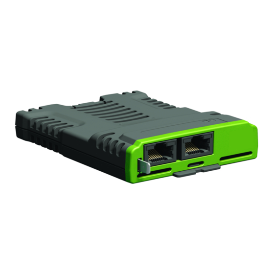
Page 7: Features / Specification
Features / specification The following features are included in the SI-PROFINET RT option module: • Dual 100 BASE-TX RJ45 connectors with support for shielded twisted pair, full- duplex 100 M bps connectivity with auto crossover correction • Both RJ45 ports operate in full duplex mode as a network switch •... -
Page 8: Mechanical Installation
Mechanical installation Before installing or removing an option module from any drive, ensure the AC supply has been disconnected for at least 10 minutes and refer to section 1 Safety information on page 4. If using a DC bus supply ensure this is fully discharged before working on any drive or option module. -
Page 9: Electrical Installation
Electrical installation Bus media The SI-PROFINET RT option module incorporates two 100 BASE-TX RJ45 interfaces operating in full duplex mode with auto crossover correction. Both ports have integrated switches and can be connected to other PROFINET devices to create a line network. Cabling considerations To ensure long-term reliability it is recommended that any cable used is tested using a suitable Ethernet cable tester, this is of particular importance when cables are... -
Page 10: Cable
Avoid excessive bending during installation, the maximum recommended bending radius is 10 times the cable diameter 75 mm (3.0 in). NOTE Cabling issues are the single most frequent cause of network downtime. • Ensure cables are correctly routed i.e. not adjacent to high-power cables etc. •... -
Page 11: Maximum Network Length
Maximum network length The main restriction imposed on Ethernet cabling is the length of a single segment of cable. The SI-PROFINET RT module has two 100 BASE-TX Ethernet ports, which support segment lengths of up to 100 m. This means that the maximum cable length which can be used between one SI-PROFINET RT port and another 100 BASE-TX port is 100 m, however it is not recommended that the full 100 m cable length is used. -
Page 12: Module Grounding
Table 4-3 SI-PROFINET RT Ethernet connections Port A / B Function Transmit + Transmit - Receive + Not used Not used Receive - 8 7 6 5 4 3 2 1 Not used Not used Module grounding SI-PROFINET RT is supplied with a grounding tag on the module that should be connected to the closest possible grounding point using the minimum length of cable. -
Page 13: Minimum Node-To-Node Cable Length
Minimum node-to-node cable length There is no minimum length of cable recommended in the Ethernet standards. To avoid possible cabling problems, it is recommended that sufficient cable length is provided to ensure adequate bend radii on cables and avoid unnecessary strain on the connectors. SI-PROFINET RT User Guide Issue Number: 2... -
Page 14: Getting Started
Getting started This chapter is intended to provide a generic guide for setting up SI-PROFINET RT on a PROFINET network. The setup flowchart (SI-PROFINET RT setup flowchart on page 17) is intended as a guide only, and is provided to detail the stages that are required to achieve a functioning network. -
Page 15: Setting The Ip Address
Setting the IP address Each device on a network must have it's own unique IP address, if the network is not to be connected to other networks or the Internet, then the assignment of the IP addresses is not critical (although using a standard system is recommended). The issue of address assignment becomes more important when connecting multiple networks together or connecting to the Internet where there is a strong possibility of address duplication unless a standard addressing system is used. -
Page 16: Subnet Mask
Table 5-2 IP address classes Class A Net ID (7 bits) Host ID (24 bits) Class B Net ID (14 bits) Host ID (16 bits) Class C Net ID (21 bits) Host ID (8 bits) Class D 1 1 0 Multicast group ID (28 bits) Class E 1 1 1... -
Page 17: Profinet Device Name
PROFINET device name Every PROFINET device must have a unique device name assigned to it during network configuration. Device names are used by the PLC to communicate with the device for RT messages (cyclic data and alarms). Without a device name, the device will not enter data exchange with the PLC. -
Page 18: Additional Features
Additional features This chapter provides information on the additional functions and features of the SI- PROFINET RT option module. Update time In contrast to some other fieldbus networks, PROFINET has no single bus cycle where the slowest device determines the update rate for all devices, PROFINET allows different update rates for each device. -
Page 19: Discovery And Configuration Protocol (Dcp)
6.2.1 Number of phases The number of phases is determined by the formula: Number Of Phases = Send Cycle / Fastest Update Rate = 8 ms / 1 ms = 8 6.2.2 Length of phase The length of each phase is determined by the formula: Length Of Phase = SendClockFactor x 31.25 µs = 32 x 31.25 µs = 1 ms Where: SendClockFactor is specified in the GSDML file as the 'MinDeviceInterval' value. - Page 20 6.3.2 Configuring the network topology for DCP In order to use the network discovery and configuration protocol, the PLC must be correctly configured and programmed with the physical network topology, the following information is intended as a guide only, for more specific information (in particular for other types of PLC's), then please consult the PLC documentation.
-
Page 21: Identification And Maintenance (I&M)
Once the PLC has been configured, if a device is replaced then the new device will be automatically configured with the original device's properties, including the device name and IP address. NOTE For the discovery protocol to work, the replacement device must not have a device name programmed, i.e. - Page 22 Software revision: 4-byte value consisting of a single character 'V' and 3 unsigned 8-bit decimal numbers indicating the software revision of the SI-PROFINET RT module. This value is taken from Pr S.00.002 of the SI-PROFINET RT module. Revision counter: 2-byte unsigned decimal number. This value is not changed by SI-PROFINET RT but can be changed by the network controller.
- Page 23 6.4.4 I&M3 Table 6-5 I&M3 Description Attribute Value (Read/Write) Descriptor (54 bytes) (User defined) Descriptor: 54-byte string used to store additional information on the location, function or maintenance status of the device. 6.4.5 I&M4 Table 6-6 I&M4 Description Attribute Value (Read/Write) Signature (54 bytes) (User defined) Signature: 54-byte octet string used to allow parameterization tools to store a security...
-
Page 24: Parameter Descriptions
Parameter descriptions Single line parameter descriptions 7.1.1 Menu 0 - Setup Parameter Range Default Type S.00.001 Module ID 0 to 65535 00.00.00.00 to S.00.002 Software Version 00.99.99.99 S.00.003 Hardware Version 00.00 to 99.99 0 to 99999999 S.00.004 Serial Number LS S.00.005 Serial Number MS 0 to 99999999... - Page 25 7.1.2 Menu 2 - PROFINET Ethernet configuration Parameter Range Default Type Initializing (0), Links Down (1), S.02.003 Network Status No Address (3), Ready (4), ND NC PT Active (5) Network Message S.02.004 0 to 65535 Msg/s ND NC PT Count S.02.006 IP Address 0.0.0.0 to 255.255.255.255...
- Page 26 7.1.3 Menu 5 - PROFINET configuration Parameter Range Default Type No Error (0), Input Mapping Error (1), Output Mapping Error (2), Configuration No Error S.05.004 Data Size Error (3), NC PT Error Parameter Configuration Error (4) Module S.05.006 Revision 0 to 65535 RO Num ND NC PT Counter S.05.007 Profile ID...
-
Page 27: Menus
Menus The table below details each of the module's internal menus. Menu Description S.00 Module information S.02 PROFINET Ethernet Configuration S.05 PROFINET Configuration S is the slot number where the module is installed. The module's menu 0 is also displayed in menu 15, 16 or 17 depending on which slot the module in installed in. - Page 28 S.00.003 Hardware version Minimum 00.00 Maximum 99.99 Default Units Type 16 Bit Volatile Update Rate Power-up write Display Format None Decimal Places Coding RO, ND, NC, PT The hardware version of the option module is in the format of ww.xx.yy.zz. S.00.004 Serial Number LS S.00.005...
- Page 29 S.00.007 Reset Module Minimum Maximum Default Units Type 1 Bit Volatile Update Rate Read every 200 ms Display Format None Decimal Places Coding RW, NC Changes to the module's configuration will not take effect until the module has been reset. To reset the module: •...
- Page 30 S.00.031 Slot Menu Number Minimum Maximum Default Units Type 8 Bit Volatile Update Rate Written on power-up Display Format None Decimal Places Coding RO, ND, PT This parameter displays the menu number of the option slot on the drive. e.g. Slot 1 - Menu 15 Slot 2 - Menu 16 Slot 3 - Menu 17...
- Page 31 S.02.006 IP Address Minimum 0.0.0.0 Maximum 255.255.255.255 Default 0.0.0.0 Units Type 32 Bit Volatile Update Rate Display Format IP address Decimal Places Coding RO, NC, PT, BU In the PROFINET environment, the controller (CONTROLLER) normally provides the IO device (PROFINET option module mounted on a drive) with its IP address, subnet mask and default gateway address.
- Page 32 S.02.011 MAC Address Minimum 0:0:0:0:0:0 Maximum FF:FF:FF:FF:FF:FF Default Units Type 64 bit volatile Update Rate Power-up write Display Format MAC address Decimal Places Coding RO, ND, NC, PT, BU Display the MAC address for the Ethernet interface as a 48 bit hexadecimal value. This is the base MAC address for the module.
- Page 33 S.05.006 Module Revision Counter Minimum Maximum 65535 Default Units Type 16 Bit Volatile Update Rate On Module Reset Display Format None Decimal Places Coding RO, ND, PT, BU A changed value of the revision counter parameter of PROFINET marks a change of hardware or its parameters.
- Page 34 S.05.009 Timeout Minimum Maximum 10000 Default Units Type 16 Bit volatile Update Rate Connect request from controller Display Format None Decimal Places Coding RW, PT, BU This parameter defines the time period in which the module must receive a cyclic data frame from the controller before any specified action is performed.
- Page 35 S.05.011 Timeout Event Destination Minimum Maximum Default Units Type 8 Bit User Save Update Rate Module reset / initialization Display Format Text Decimal Places Coding RW, BU This parameter defines the Event task destination if a specified Event task in a compatible module is set to run.
-
Page 36: Diagnostics
Diagnostics Overview This section provides basic diagnostic information intended to resolve the most common problems encountered when setting up an SI-PROFINET RT option module. Link LEDs Each of the Ethernet ports provide a status LED for diagnostics and information purposes. Figure 8-1 SI-PROFINET RT connections Link LEDs Ethertnet... - Page 37 Trip Description SlotX HF The drive has detected that an option module is present but is unable to communicate with it due to a hardware fault. SlotX Error User trip generated by the option module SlotX Not Fitted This trip will occur if a drive slot was previously configured with an option module but on power up, no option module was detected.
- Page 38 PROFINET error codes If the option module detects a PROFINET error during operation, it will force a trip on the drive and provide a sub-trip string for a clearer definition of the trip. The following table lists all possible PROFINET error codes: Value Text Description...
- Page 39 Diagnostics flowchart Start Check RTE controller is sending Is port LED data off ? Connect Ethernet cable Is Ethernet cable Is port LED connected ? flashing ? Test Ethernet cable Check RTE Is RTE controller controller setup is data correct ? correct Check RTE controller is...
-
Page 40: Glossary
Glossary Address: This is the unique network identification given to a networked device to allow communication on a network. When a device sends or receives data the address is used to determine the source and the destination of the message. ASCII (American Standard Code for Information Interchange): A standard character encoding mechanism established by ANSI to provide compatibility between data systems and services. - Page 41 Channel: A data link which connects two devices allowing them to communicate with each other. Character: Any letter, number, punctuation mark or other sign contained in a message, including characters for control functions and for special symbols. Checksum: The sum of a group of data provided with the group, for checking purposes. Control Character: A non-printing character used to initiate, modify, or stop a control function.
- Page 42 DHCP (Dynamic Host Configuration Protocol): This is a protocol used to allocate dynamic IP addresses to network devices from a central server. DNS (Domain Name Server): This is a server that is used to convert a URL such as "www.controltechniques.com" to an IP address such as 129.254.254.106. Double word: A 32-bit word, this may be signed or unsigned.
- Page 43 IP subnet: A part of an IP network that consists of a range of addresses that may be accessed by all devices on the same network directly. ISO (International Standards Organization): The International, voluntary standards organization, closely aligned with the CCITT perhaps best noted for its OSI model and OSI communications protocol.
- Page 44 OSI Model (Open Systems Interconnection Model): The 7-layer reference model recommended by the ISO to provide a logical structure for network operations protocol. Parity Bit: An error-checking bit whose binary value (0 or 1) depends on whether the sum of bits with the value 1 in the unit of data being checked is odd or even. If the total number of bits with value 1, including the parity bit (or bits), is even, the unit of data is said to have even parity;...
- Page 45 Subnet: A part of a network that has IP addresses in the same range. Devices on the same subnet may communicate directly with other devices on the same subnet without the use of a gateway. Subnet mask: Defines which part of the IP address constitutes the subnet address and which part constitutes the host device address.
- Page 46 Index Bus media ....................9 Cable ......................10 Cabling considerations .................9 Cautions .......................4 Compliance with regulations ................5 Conventions used in this guide ..............7 Cyclic data ..................7, 42, 44 Date code format ..................6 Diagnostics flowchart .................39 Electrical safety ....................4 Environmental limits ..................5 Features / specification ................7 General installation ..................8 Glossary .....................40 GSDML file ....................14...
- Page 47 Segment .....................11 Setup flowchart ...................17 SI-PROFINET RT terminal descriptions .............11 Stored charge ....................5 Subnet mask ....................16 System design and safety of personnel ............4 What is PROFINET ..................6 SI-PROFINET RT User Guide Issue Number: 2...
- Page 48 0478-0125-02...
Need help?
Do you have a question about the SI-PROFINET RT 0478-0125-02 and is the answer not in the manual?
Questions and answers