
Related Manuals for Balluff BNI PBS-507-001-Z011


Summary of Contents for Balluff BNI PBS-507-001-Z011
- Page 1 BNI PBS-506-001-Z011 BNI PBS-507-001-Z011 IP67 Module, Profibus IO-Link Master User´s Guide...
-
Page 2: Table Of Contents
Startup 7.1. Profibus-Address Adressing 7.2. Configuration GSD file Header module Structure of the header module Header byte coding Length byte coding Data modules Data module coding Process data coding 7.3. Setting parameters Norm-specific parameters Station status WD_Fact_1 and WD_Fact_2 www.balluff.com... -
Page 3: Example
Balluff Network Interface Profibus MinTSDR Ident_Number_High Ident_Number_Low Group_Ident User parameters Configuration examples Example 1 Example 2 Example 3 7.4. Integration in project planning software Installing the GSD file Requirements Integration of the module Define properties Slot configuration Diagnostics 8.1. Function indicators... -
Page 4: Notes For The User
This symbol indicates general notes. Note! This symbol indicates a security notice which most be observed. 1.5. Abbreviations O-Port Digital output port Binär coded switch Balluff Network Interface Electromagnetic Compatibility I-Port Digital input port Functions earth GSD file Generic Station Description... -
Page 5: Safety
Balluff Network Interface Profibus Safety This guide describes The BNI PBS-… serves as a decentralized input/output module for 2.1. Intended use connecting to a Profibus network. 2.2. General safety Installation and startup notes Installation and startup are to be performed only by trained specialists. Any damage resulting from unauthorized manipulation or improper use voids the manufacturer’s... -
Page 6: Getting Started
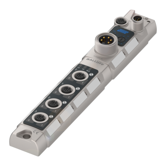
Ground connection M12 Profibus IN Address switches Supply POWER I-/O- port 0 I-/O- port 1 IO-Link port 2 IO-Link port 3 I-/O-/IO-Link port LED 10 Status LED communication / module 11 Label 12 M12 Profibus OUT 13 Mounting hole www.balluff.com... -
Page 7: Connection Overview Bni Pbs-507-001
Balluff Network Interface Profibus Getting Started 3.2. Connection overview BNI PBS-507-001.. BNI PBS-507-001-Z011 Ground connection M12 Profibus IN Address switches Supply POWER I-/ O-/ IO-Link port 0 I-/ O-/ IO-Link port 1 I-/ O-/ IO-Link port 2 I-/ O-/ IO-Link port 3... -
Page 8: Basic Knowledge
Basic knowledge 4.1. Product Balluff Network Interface BNI PBS-...: description Used for connecting sensors/actuators to a Profibus-DP network. Sensors/actuators can be connected through 4 standard I/O ports. Connection to Profibus using 2 × M12×1 round connectors. ... -
Page 9: Communication Mode
Balluff Network Interface Profibus Basic knowledge 4.4. Communication Process data (cyclical): mode The GSD file provides different data modules for representing the sensor map: Inputs: 1 byte – 32 bytes Outputs: 1 byte – 32 bytes Or combined input/output modules Deterministic time behavior: ... -
Page 10: Technical Data
1, 2.x, 3 5.5. Operating -5 C … 70°C Operating temperature conditions -25 C … 70°C Storage temperature - EN 61000-4-2/3/4/5/6 - Severity level 4A/3A/4B/2A/3A - EN 55011 - Gr. 1, Kl. A Shock / vibration EN 60068 Part 2-6/27 www.balluff.com... -
Page 11: Installation
Balluff Network Interface Profibus Installation 6.1. Mechanical connection The BNI PBS-... module can be connected directly to a mounting wall or to a machine. Be sure that the mounting base is flat to prevent any mechanical stress on the Device housing. -
Page 12: Supply Voltage
Module and connected sensors are supplied by the sensor supply. The output stages are supplied by the actuator supply, except pin 4 of the IO-Link output stage. These are supplied by the sensor supply. Note, Tip! Use different power sources for the sensor/bus and actuator if possible. www.balluff.com... -
Page 13: Bus Connection
Balluff Network Interface Profibus Installation 6.3. Bus connection The bus connection is made using the M12 sockets Profibus IN and Profibus OUT. The address is set on the address switch. Profibus OUT Profibus IN Function (M12, B-coded, (M12, B-coded, female) -
Page 14: Startup
The Device data required for project planning are stored in GSD files (Generic Station Description). The GSD files are available in 2 languages for downloading over the Internet (www.balluff.com). The data modules of an IO-Link module are represented in the project planning software by slot. -
Page 15: Header Module
Balluff Network Interface Profibus Startup Header module First the header module is inserted into the configuration. The header module is coded according to the special identification format. Header modules in this coding are used for identification and parameter setting and have a data width of 1 bytes input of 1 bytes input/output data. -
Page 16: Data Module Coding
C1hex83hex9Fhex05hex IOL_I/O_16/16 byte 16 Byte 16 Byte C1hex8Fhex8Fhex05hex IOL_I/O_24/24 byte 24 Byte 24 Byte C1hex97hex97hex05hex IOL_I/O_32/32 byte 32 Byte 32 Byte C1hex9Fhex9Fhex05hex Note, Tip! Project planning software offers mostly graphical assistance in configuration, the configuration string is automatically created. www.balluff.com... -
Page 17: Process Data Coding
Balluff Network Interface Profibus Startup Additional Module Additional Module Data width Coding Input Output Communication state 1 Byte 10hex IO-Link diagnoses enable 1 Byte 10hex Stations diagnostic 1 Byte 10hex Peripherie fault 1 Byte 10hex Sensor short circuit 1 Byte... -
Page 18: Setting Parameters
Timeout (TWD) = 10 ms x WD_Fact_1 x WD_Fact_2. Times from 10 ms to 650 s can be set. WD_Fact_1 Byte 1 0 ... 255 (0x00 ... 0xFF) WD_Fact_2 Byte 2 0 ... 255 (0x00 ... 0xFF) www.balluff.com... -
Page 19: Mintsdr
Balluff Network Interface Profibus Startup MinTSDR MinTSDR: Minimum time before sending a Device reply (in Tbits). The standard prescribes a minimum value of 11 Tbits. The value must be less than MaxTSDR Byte 1 0, 11 ... 255 (0x00, 0x0B ... 0xFF) -
Page 20: User Parameters
00000100 IO-Link-Port IO parameters for an IO-Link port: Byte Meaning Module Identifier / Validation type Cycle Time Process data offset Process data window length Vendor ID 0 Vendor ID 1 Device ID 0 Device ID 1 Device ID 2 www.balluff.com... -
Page 21: Configuration Examples
Balluff Network Interface Profibus Startup Configuration The structure of the user parameters depends on the port configuration of the Profibus examples IO-Link Master module. The following examples show the structure of the user parameters for various port configurations Example 1 Profibus IO-Link Master Port 0 –... -
Page 22: Example 2
0x00 Cycle Time 0x00 Process data offset 0x10 Process data window length IO-Link module 0x00 Vendor ID 0 16 byte IN/16 byte Out 0x00 Vendor ID 1 0x00 Device ID 0 0x00 Device ID 1 0x00 Device ID 2 www.balluff.com... -
Page 23: Example
Balluff Network Interface Profibus Startup Example 3 Profibus IO-Link Master Port 0 – 3 Pin 4: Configured as standard I/O port Port 0 – 3 Pin 2: Configured as standard I/O port Port 4 Pin 4: Configured as IO-Link port... -
Page 24: Integration In Project Planning Software
The GSD file is installed. When the process is finished, a message appears. • Confirm the message and close the window. • Select the menu command „Tools | Update catalog“. The modules are displayed in the project tree. www.balluff.com... -
Page 25: Requirements
Balluff Network Interface Profibus Startup Requirements For the integration of a Profibus Device a configuration at the PLC and the DP interface is required. Integration of the Select the Profibus Device from the catalogue and integrate it into the Profibus system. -
Page 26: Define Properties
The function of the single pins can be defined When the IO-Link interface is activated, in the slots (2…5) the corresponding IO-Link Slot configuration module has to be placed with the right process date length. Additional modules can be placed in slot 6. www.balluff.com... -
Page 27: Diagnostics
Balluff Network Interface Profibus Diagnostics 8.1. Function The status of the supply voltages is indicated by the status LED´s 1 to 5. indicators LED indicators Status LEDs Indicator Function Green US power supply sensor ok Green UA power supply actuator ok... -
Page 28: Diagnostics Telegram
The DP Device always sets the bit to 0. The DP Master sets it to 1 if the DP Device was parameterized by a different Master (Lock from another Master, here: Address in byte 3 not equal to FFhex and not equal to its own address). www.balluff.com... -
Page 29: Status 2
Balluff Network Interface Profibus Diagnostics Status 2 Byte 1, Status 2 Meaning Prm_req The DP Device always sets the bit to 1 if it needs to be reconfigured and parameterized. The bit remains set until parameterizing is done. Stat_Diag (statistic diagnostic) The Device sets the bit to 1 if for example it can not send valid data. -
Page 30: Device-Specific Diagnostics
Bit 6 Bit 5 Bit 4 Bit 3 Bit 2 Bit 1 Bit 0 Module Module 0-3 Module 4-7 Status module Valid data from this module Invalid data, error in the module Invalid data, wrong module Invalid data, missing module www.balluff.com... -
Page 31: Module-Specific Diagnostics
Balluff Network Interface Profibus Diagnostics 8.5. Module-specific Byte Diagnostics Header Module Note, Tip! When coding the module-specific diagnostics: 1 = activated, 0 = deactivated Coding of the module-specific Diagnostic Header Byte 0, Header Meaning 6 … 7 Header 01: modulespecific diagnostic 0 …... -
Page 32: Channel-Specific Diagnostics
27: Sensor has wrong configuration 8: Lower limit undershot 28: Low voltage actuator supply 9: Fault 29-31: Vendor specific 5 … 7 Format (Decimal): 1: Bit 4: Byte 2: 2 Bit 5: Word 3: 4 Bit 6: 2 Words www.balluff.com... -
Page 33: Appendix
Balluff Network Interface Profibus Appendix 9.1. Included material The BNI PBS consists of the following components: IO-block 4 blind plugs M12 Ground strap Screw M4x6 20 labels 9.2. Ordercode BNI PBS-50x-001-Z011 Balluff Network Interface Profibus... -
Page 34: Ascii-Tabelle
Ctrl O Ctrl P Ctrl Q < Ctrl R Ctrl S > Ctrl T Ctrl U Ctrl V Ctrl W Ctrl X Ctrl Y Ctrl Z Ctrl [ Ctrl \ Ctrl ] Ctrl ^ Ctrl _ „ & ‘ www.balluff.com... -
Page 35: Notes
Notes www.balluff.com... - Page 36 Notes www.balluff.com...
-
Page 37: Www.balluff.com
Balluff GmbH Schurwaldstrasse 9 73765 Neuhausen a.d.F. Germany Tel. +49 7158 173-0 Fax +49 7158 5010 www.balluff.com balluff@balluff.de...
Need help?
Do you have a question about the BNI PBS-507-001-Z011 and is the answer not in the manual?
Questions and answers