
Related Manuals for Balluff BNI IOL-252-000-Z013


Summary of Contents for Balluff BNI IOL-252-000-Z013
- Page 1 BNI IOL-252-000-Z013 BNI IOL-252-S01-Z013 BNI IOL-256-000-Z013 BNI IOL-256-S01-Z013 User’s Guide...
-
Page 2: Table Of Contents
IO-Link interface Connecting the actuator hub Module version Actuator interface IO-Link Interface IO-Link Data 4.1. Process data / Input data BNI IOL-252-000-Z013 BNI IOL-252-S01-Z013 BNI IOL-256-000-Z013 BNI IOL-256-S01-Z013 4.2. Process data / Output data BNI IOL-252-xxx-Z013 BNI IOL-256-xxx-Z013 Parameter Data / Request data... - Page 3 Appendix 6.1. Typ Code 6.2. Order information 6.3. Scope of delivery www.balluff.com...
-
Page 4: General
Balluff Network Interface / IO-Link BNI IOL-25x-xxx-Z013 General 1.1. Structure of the This manual is structured such that one chapter is builds on the other. manual Chapter 1: General Chapter 2: Basic safety instructions ……. 1.2. Typographical The following typographical conventions are used in this manual. -
Page 5: Safety
Note voltage Disconnect all power before servicing equipment. Note In the interest of product improvement, the Balluff GmbH reserves the right to change the specifications of the product and the contents of this manual at any time without notice. www.balluff.com... -
Page 6: Getting Started
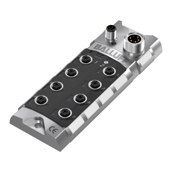
Balluff Network Interface / IO-Link BNI IOL-25x-xxx-Z013 Getting Started 3.1. Connection overview Connection overview 1 Mounting hole 9 Mounting hole 2 Label 10 Pin/Port LED: Signal status 3 Supply voltage connection 11 Standard output port 6 4 Status LED 12 Standard output port 4... -
Page 7: Mechanical Connection
Connection protection ground to FE terminal, if present. actuator hub Connecting the power supply of the segments. Connect the incoming IO-Link line to the actuator hub. Note A standard 3 wire sensor cable is used for connection to the host IO-Link master. www.balluff.com... -
Page 8: Module Version
Balluff Network Interface / IO-Link BNI IOL-25x-xxx-Z013 Getting Started Module version Hub versions Digital port BNI IOL-252-000-Z013 8 outputs BNI IOL-252-S01-Z013 8 outputs with additional diagnostics BNI IOL-256-000-Z013 16 outputs BNI IOL-256-S01-Z013 16 outputs with additional diagnostics Actuator interface Standard output port ( M12, A-coded, female) -
Page 9: Io-Link Interface
IO-Link Interface IO-Link Data BNI IOL-252-000-Z013 Data transmission rate COM2 (38,4 kBaud) Frame type Minimal cycle time 3 ms Process data cycle time 3 ms, at minimal cycle time Process data length 1 Bytes output BNI IOL-252-S01-Z013 Data transmission rate... -
Page 10: Bni Iol-252-S01-Z013
Balluff Network Interface / IO-Link BNI IOL-25x-xxx-Z013 IO-Link Interface BNI IOL-252-S01- Byte 0 Byte 1 Z013 Byte 2 Byte 3 Signal port (x): x.0: Pin 4, X.1: Pin 2 BNI IOL-256-000- No input data Z013 BNI IOL-256-S01- Byte 0 Byte 1... -
Page 11: Process Data / Output Data
X.1: Pin 2 4.2. Process data / Output data BNI IOL-252-xxx- Byte 0 Z013 Signal port (x): x.0: Pin 4, X.1: Pin 2 BNI IOL-256-xxx- Byte 0 Byte 1 Z013 Signal port (x): x.0: Pin 4, X.1: Pin 2 www.balluff.com... -
Page 12: Parameter Data / Request Data
Balluff Network Interface / IO-Link BNI IOL-25x-xxx-Z013 IO-Link Interface Parameter Data / SPDU Request data Object name Length Range Default value Sub- Index Index Index Vendor ID 2 Byte 0378 050705 05070A Device ID 3 Byte 050710 05070B Vendor name... -
Page 13: Voltage Monitoring
Short circuit port x.0 = Pin 4 In case of BNI IOL-256-xxx-Z013 Short circuit at signal Byte 0 Byte 1 port on port x Short circuit port x.0 = Pin 4 Short circuit port x.1 = Pin 2 www.balluff.com... -
Page 14: Actuator Warning
Balluff Network Interface / IO-Link BNI IOL-25x-xxx-Z013 IO-Link Interface Actuator In case of BNI IOL-252-xxx-Z013 warning Byte 0 Actuator warning at signal port on port x Actuator warning port x.0 = Pin 4 In case of BNI IOL-256-xxx-Z013 Actuator warning at signal port on... -
Page 15: Feedback
Feedback port x.1 = Pin 2 Note Actuator short circuit: overload or short circuit of the output signal against 0V. Actuator warning signal: short circuit of the output signal against +24V. Suppress Byte 0 events 0 – Release Event 1 – Suppress Event www.balluff.com... -
Page 16: Errors
Balluff Network Interface / IO-Link BNI IOL-25x-xxx-Z013 IO-Link Interface 4.3. Errors Error Code Additional Code Device application Index not available error 0x80 0x11 Device application Subindex not available error 0x80 0x12 Device application Value out of range error 0x80 0x30 4.4. -
Page 17: Technical Data
Storage temperature EMV / EMC EN 61000-4-2/3/4/5/6 Severity level 2B/3A/4B/2B/3A EN 60068-2-6, EN 60068-2-27 Vibration/shock EN 60068-2-29, EN 60068-2-64 5.4. Electrical data Supply voltage 18….30.2 V DC, per EN 61131-2 Ripple < 1% ≤ 90 mA Current consumption without load www.balluff.com... -
Page 18: Led Indicators
Balluff Network Interface / IO-Link BNI IOL-25x-xxx-Z013 Technical data 5.5. LED indicators LED 1-6, Status LED Port/Pin LED: Status output ports Status LED Indicator Function LED 1 Green / Red Supply module ok / Undervoltage LED 3 Green / Red... -
Page 19: Appendix
Appendix 6.1. Typ Code BNI IOL-25x-xxx-Z013 Balluff Network Interface IO-Link Interface Functions 252 = 8 outputs 256 = 16 outputs Versions 000 = Standard version S01 = version with additional diagnostics Mechanical design Z013 = Die-cast zinc housing, matte nickel plated... -
Page 20: Www.balluff.com
Balluff Network Interface / IO-Link BNI IOL-25x-xxx-Z013 www.balluff.com Balluff GmbH Schurwaldstrasse 9 73765 Neuhausen a.d.F. Germany Tel. +49 7158 173-0 Fax +49 7158 5010 www.balluff.com balluff@balluff.de...
Need help?
Do you have a question about the BNI IOL-252-000-Z013 and is the answer not in the manual?
Questions and answers