Moxa Technologies NPort IA5000A Series User Manual
Hide thumbs
Also See for NPort IA5000A Series:
- User manual (194 pages) ,
- Quick installation manual (9 pages)

Related Manuals for Moxa Technologies NPort IA5000A Series


Summary of Contents for Moxa Technologies NPort IA5000A Series
- Page 1 NPort IA5000A Series User’s Manual Third Edition, April 2013 www.moxa.com/product © 2013 Moxa Inc. All rights reserved. Reproduction without permission is prohibited.
- Page 2 NPort IA5000A Series User’s Manual The software described in this manual is furnished under a license agreement and may be used only in accordance with the terms of that agreement. Copyright Notice Copyright ©2013 Moxa Inc. All rights reserved. Reproduction without permission is prohibited.
-
Page 3: Table Of Contents
Table of Contents Introduction ............................1-1 Overview ............................1-2 Package Checklist ..........................1-2 Product Features ..........................1-2 Product Specifications ......................... 1-3 Getting Started ..........................2-1 Panel Layout ............................2-2 NPort IA5150A Series ........................2-2 NPort IA5250A ..........................2-2 NPort IA5450A ..........................2-3 Connecting the Hardware ........................ - Page 4 Change Password ..........................5-36 Load Factory Default ......................... 5-37 Save/Restart ............................ 5-37 Configuring NPort Administrator ....................... 6-1 Overview ............................6-2 Installing NPort Administrator ......................6-2 Configuration ............................. 6-4 Broadcast Search ........................6-4 Unlock Password Protection ......................6-5 Configuring the NPort IA5000A ..................... 6-6 Upgrading the Firmware .......................
-
Page 5: Introduction
Introduction Welcome to the NPort IA5000A Series of industrial serial device servers. The following topics are covered in this chapter: Overview Package Checklist Product Features Product Specifications... -
Page 6: Overview
Not only has the hardware been upgraded, but more flexible and user-friendly software has been added. The NPort IA5000A series of device servers deliver easy and reliable serial-to-Ethernet connectivity for the industrial automation market. The NPort IA5000A series is designed to allow any serial device to connect to an Ethernet network. -
Page 7: Product Specifications
NPort IA5000A Series Introduction Product Specifications Ethernet Interface Number of Ports: 2 Speed: 10/100 Mbps, auto MDI/MDIX Connector: 8-pin RJ45 Magnetic Isolation Protection: 1.5 kV built-in Serial Interface Number of Ports: NPort® IA5150A: 1 NPort® IA5250A: 2 NPort® IA5450A: 4... - Page 8 NPort IA5000A Series Introduction Environmental Limits Operating Temperature: Standard Models: 0 to 60°C (32 to 140°F) Wide Temp. Models: -40 to 75°C (-40 to 167°F) Operating Humidity: 5 to 95% RH Storage Temperature: -40 to 85°C (-40 to 185°F) Power Requirements Input Voltage: 12 to 48 VDC (10.8 to 60 VDC)
-
Page 9: Getting Started
Getting Started In this chapter, we give instructions on installing the NPort IA5000A device servers. Software installation is covered in subsequent chapters. The following topics are covered in this chapter: Panel Layout Connecting the Hardware Wiring Requirements ... -
Page 10: Panel Layout
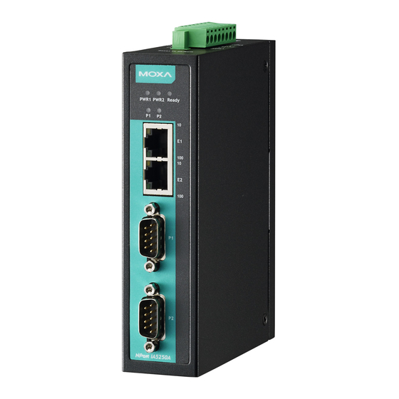
NPort IA5000A Series Getting Started Panel Layout NPort IA5150A Series NPort IA5250A... -
Page 11: Nport Ia5450A
Wiring Requirements ATTENTION Safety First! Be sure to disconnect the power cord before installing and/or wiring your NPort IA5000A Series. Wiring Caution! Calculate the maximum possible current in each power wire and common wire. Observe all electrical codes dictating the maximum current allowable for each wire size. -
Page 12: Connecting The Power
“Ready” LED will show a solid red color until the system is ready, at which time the “Ready” LED will change to a green color. Grounding the NPort IA5000A Series Grounding and wire routing helps limit the effects of noise caused by electromagnetic interference (EMI). Run the ground connection from the ground screw to the grounding surface prior to connecting devices. -
Page 13: Led Indicators
It is improbable for a single pull high/low resistor value to suit all the various environments and this is why the NPort IA5000A series provides DIP switches for setting the pull high/low resistor values for each serial port. -
Page 14: Initial Ip Address Configuration
Initial IP Address Configuration When setting up your NPort IA5000A for the first time, the first thing you should do is configure the IP address. This chapter introduces the methods that can be used to configure the device server’s IP address. Select one of the initial IP Address configuration methods to configure the NPort IA5000A’s IP Address. -
Page 15: Initializing The Nport's Ip Address
NPort IA5000A. See Chapter 5 for details on how to install NPort Administration Suite, and how to use this suite of useful utilities to set up IP addresses and configure your NPort IA5000A Series serial device servers. You can make use of the ARP (Address Resolution Protocol) command to set up an IP address for your NPort IA5000A. -
Page 16: Telnet Console
NPort IA5000A Series Initial IP Address Configuration Take the following steps to use ARP to configure the IP address: 1. Obtain a valid IP address for your NPort IA5000A from your network administrator. 2. Obtain the NPort IA5000A’s MAC address from the label on its bottom panel. - Page 17 NPort IA5000A Series Initial IP Address Configuration 4. Type 2 to select Network settings, and then press Enter. 5. Type 1 to select IP address and then press Enter. 6. Use the Backspace key to erase the current IP address, type in the new IP address, and then press Enter.
- Page 18 NPort IA5000A Series Initial IP Address Configuration 7. Press any key to continue… 8. Type m and then press Enter to return to the main menu. 9. Type s and then press Enter to Save/Restart the system.
-
Page 19: Serial Console (19200, N, 8, 1)
NPort IA5000A Series Initial IP Address Configuration 10. Type y and then press Enter to save the new IP address and restart the NPort IA5000A. Serial Console (19200, n, 8, 1) You may use the RS-232 console port to set up the IP address for the NPort IA5000A. We suggest using PComm Terminal Emulator, which is available free of charge as part of the PComm Lite program suite, to carry out the installation procedure, although other similar utilities may also be used. - Page 20 NPort IA5000A Series Initial IP Address Configuration 5. If you select Dumb Terminal as the terminal type, some of the console functions—especially the “Monitor” function—may not work properly. 6. Press the “ ` ” key continuously and then power on the NPort IA5000A.
- Page 21 NPort IA5000A Series Initial IP Address Configuration 9. Start configuring the IP address under Network Settings. Refer to step 4 in the Telnet Console section for the rest of the IP settings.
-
Page 22: Choosing The Proper Operation Mode
Choosing the Proper Operation Mode In this chapter, we describe the NPort IA5000A various Toperation modes. The options include an operation mode that uses a driver installed on the host computer, and operation modes that rely on TCP/IP socket programming concepts. After choosing the proper operation mode in this chapter, refer to Chapter 5 for detailed configuration parameter definitions. -
Page 23: Overview
NPort IA5000A Series Choosing the Proper Operation Mode Overview NPort IA5000A serial device servers network-enable traditional RS-232/422/485 devices, in which a Serial Device Server is a tiny computer equipped with a CPU, real-time OS, and TCP/IP protocols that can bi-directionally translate data between the serial and Ethernet formats. Your computer can access, manage, and configure remote facilities and equipment over the Internet from anywhere in the world. -
Page 24: Rfc2217 Mode
NPort IA5000A Series Choosing the Proper Operation Mode ATTENTION Real COM Mode allows several hosts to have access control over the same NPort IA5000A. The driver that comes with your NPort IA5000A controls host access to attached serial devices by checking the host’s IP address. -
Page 25: Udp Mode
NPort IA5000A Series Choosing the Proper Operation Mode UDP Mode Compared to TCP communication, UDP is faster and more efficient. In UDP mode, you can not only unicast but also multicast data from the serial device to multiple host computers, and the serial device can also receive data from multiple host computers, making this mode ideal for message display applications. -
Page 26: Reverse Telnet Mode
NPort IA5000A Series Choosing the Proper Operation Mode Reverse Telnet Mode Console management is commonly used by connecting to Console/AUX or COM ports of routers, switches, and UPS units. Rtelnet works the same as RAW mode in that only one TCP port is listened to after booting up. The system then waits for a host on the network to initiate a connection. -
Page 27: Web Console Configuration
Web Console Configuration The Web Console is the most user-friendly method available to configure the NPort IA5000A. In this chapter, we will introduce the Web Console function groups and function definitions. The following topics are covered in this chapter: Opening Your Browser ... -
Page 28: Opening Your Browser
NPort IA5000A Series Web Console Configuration Opening Your Browser 1. Open your browser with the cookie function enabled. (To enable your browser for cookies, right click on your desktop Internet Explorer icon, select Properties, click on the Security tab, and then select either Enable or Prompt as shown in the figure below.) - Page 29 NPort IA5000A Series Web Console Configuration 2. The following sections introduce these two convenient functions and the other settings listed in the Main Menu on the left of the page. ATTENTION If your password, the ONLY way to start configuring the NPort IA5000A is to load the factory defaults by using the "Reset to default"...
- Page 30 NPort IA5000A Series Web Console Configuration Operating Settings to select suitable settings. 3. In the Step 3/3, you can modify the serial settings. 4. Review your settings on the Finish Settings page. If you are sure they are correct, then click the Save/Restart button to restart the device with these new settings.
-
Page 31: Export/Import
NPort IA5000A Series Web Console Configuration Export/Import Export/Import allows you to back up and recover your settings. Click Export, to store all configuration data into a default file, <Servername>.txt. Click the Import button to upload a configuration file to the NPort IA5000A. -
Page 32: Network Settings
NPort IA5000A Series Web Console Configuration Telnet console Setting Factory Default Necessity Enable or Disable Enable Required ATTENTION If you disable both the “Web console” and “Telnet console,” you can still use the NPort Administrator to configure the NPort IA5000A device servers either locally or remotely over the network. Refer to Chapter 6 for more details. - Page 33 NPort IA5000A Series Web Console Configuration IP address Setting Factory Default Necessity E.g., 192.168.1.1 (IP 192.168.127.254 Required addresses in the form x.x.x.0 and x.x.x.255 are invalid.) An IP address is a number assigned to a network device (such as a computer), which works as a permanent address on the network.
-
Page 34: Snmp Settings
NPort IA5000A Series Web Console Configuration DNS server 2 configuration items to configure the IP address of the DNS server; DNS Server 2 is included for use when DNS sever 1 is unavailable. The NPort IA5000A acts as a DNS client by actively querying the DNS server for the IP address that is associated with a particular domain name. -
Page 35: Serial Settings
NPort IA5000A Series Web Console Configuration Auto report to IP Setting Factory Default Necessity E.g., 192.168.1.1 or None Optional (IP addresses in the form of x.x.x.0 and x.x.x.255 are invalid.) Reports generated by the Auto report function will be automatically sent to this IP address. -
Page 36: Serial Parameters
NPort IA5000A Series Web Console Configuration Port alias Setting Factory Default Necessity 1 to 15 characters None Optional (E.g., PLC-No.1) “Port alias” is included to allow easy identification of the serial devices that are connected to the NPort IA5000A’s serial ports. -
Page 37: Operating Settings
NPort IA5000A Series Web Console Configuration Operating Settings Click Operating Settings, under Main Menu, to display the operating settings of the NPort IA5000A’s serial ports. Real COM Mode TCP alive check time Setting Factory Default Necessity 0 to 99 min... - Page 38 NPort IA5000A Series Web Console Configuration Max connection is usually used when the user needs to receive data from different hosts simultaneously. The factory default is 1, this means that only one specific host can access this NPort IA5000A, and the Real COM driver on that host will have full control over the port.
- Page 39 NPort IA5000A Series Web Console Configuration Delimiter 2 Setting Factory Default Necessity 00 to FF (hex) None Optional Once the NPort IA5000A receives both delimiters through its serial port, it immediately packs all data currently in its buffer and sends it to the NPort IA5000A’s Ethernet port.
-
Page 40: Rfc2217 Mode
NPort IA5000A Series Web Console Configuration RFC2217 Mode TCP alive check time Setting Factory Default Necessity 0 to 99 min 7 min Optional 0 min: TCP connection is not closed due to an idle TCP connection. 1 to 99 min: The NPort IA5000A automatically close the TCP connection if there is no TCP activity during this given time. - Page 41 NPort IA5000A Series Web Console Configuration Delimiter process Setting Factory Default Necessity Do Nothing, Do Nothing Optional Delimiter + 1, Delimiter + 2, Strip Delimiter [Delimiter + 1] or [Delimiter + 2]: The data will be transmitted when an additional byte (for Delimiter +1), or an additional 2 bytes (for Delimiter +2) of data is received after receiving the Delimiter.
-
Page 42: Tcp Server Mode
NPort IA5000A Series Web Console Configuration TCP Server Mode TCP alive check time Setting Factory Default Necessity 0 to 99 min 7 min Optional 0 min: TCP connection is not closed due to an idle TCP connection. 1 to 99 min: The NPort IA5000A will automatically close the TCP connection if there is no TCP activity during this given time. - Page 43 NPort IA5000A Series Web Console Configuration Max connection Setting Factory Default Necessity 1, 2, 3, 4, 5, 6, 7, 8 Required Max connection is usually used when the user needs to receive data from different hosts simultaneously. The factory default only allows 1 connection at a time.
- Page 44 NPort IA5000A Series Web Console Configuration ATTENTION Delimiter 2 is optional. If left blank, then Delimiter 1 alone trips the clearing of the buffer. If the size of the serial data received is greater than 1 KB, the NPort IA5000A will automatically pack the data and send it to the Ethernet.
-
Page 45: Tcp Client Mode
NPort IA5000A Series Web Console Configuration Command port Setting Factory Default Necessity 1 to 65535 Optional The “Command port” is a listening TCP port that received IP-Serial Lib commands from the host. In order to prevent a TCP port conflict with other applications, the user can set the Command port to another port as needed. - Page 46 NPort IA5000A Series Web Console Configuration This parameter defines the maintenance status as Closed or Listen for the TCP connection. The connection is closed if there is no incoming or outgoing data through the serial port during the specific Inactivity time.
- Page 47 NPort IA5000A Series Web Console Configuration Delimiter process Setting Factory Default Necessity Do Nothing, Do Nothing Optional Delimiter + 1, Delimiter + 2, Strip Delimiter Delimiter + 1 or Delimiter + 2: The data will be transmitted when an additional byte (for Delimiter +1), or an additional 2 bytes (for Delimiter +2) of data is received after receiving the Delimiter.
- Page 48 NPort IA5000A Series Web Console Configuration ATTENTION The Destination IP address parameter can use both IP address and Domain Name. For some applications, the user may need to send the data actively to the remote destination domain name. Designated Local Port 1/2/3/4...
-
Page 49: Udp Mode
NPort IA5000A Series Web Console Configuration UDP Mode Packing length Setting Factory Default Necessity 0 to 1024 Optional Default = 0, The Delimiter Process will be followed, regardless of the length of the data packet. If the data length (in bytes) matches the configured value, the data will be forced out. The data length can be configured for 0 to 1024 bytes. - Page 50 NPort IA5000A Series Web Console Configuration Delimiter + 1 or Delimiter + 2: The data will be transmitted when an additional byte (for Delimiter +1), or an additional 2 bytes (for Delimiter +2) of data is received after receiving the Delimiter.
-
Page 51: Udp Multicast
NPort IA5000A Series Web Console Configuration UDP Multicast A multicast is a packet sent by one host to multiple hosts. In multicast, each host that belongs to a specific multicast group will receive multicast packets for that group. To configure a host as a multicast receiver over the Internet, it must inform the routers on its LAN. -
Page 52: Ethernet Modem Mode
NPort IA5000A Series Web Console Configuration Destination IP address Setting Factory Default Necessity IP address or Domain Name blank Optional (E.g., 192.168.1.1) TCP port No. 4001 Required The Pair Connection “Master” will contact the network host that has this IP address. Data will be transmitted through the port No. - Page 53 NPort IA5000A Series Web Console Configuration Dial-in The NPort IA5000A listens for a TCP/IP connection request from the remote Ethernet modem or host. NPort IA5000A’s response depends on the ATS0 value, as outlined below. ATS0=0 (default): The NPort IA5000A will temporarily accept the TCP connection and then send the “RING” signal out through the serial port.
- Page 54 NPort IA5000A Series Web Console Configuration 2=ring 3=No carrier 4=error Reset (disconnect, enter command mode and restore the flash settings) AT&C Serial port DCD control AT&C0=DCD always on AT&C1=DTE detects connection by DCD on/off (default) AT&D Serial port DTR control AT&D0=recognize DTE always ready AT&D1, AT&D2=reply DTE when DTR...
-
Page 55: Reverse Telnet Mode
NPort IA5000A Series Web Console Configuration Reverse Telnet Mode TCP alive check time Setting Factory Default Necessity 0 to 99 min 7 min Optional 0 min: The TCP connection will not be closed due to an idle TCP connection. 1 to 99 min: The NPort IA5000A automatically closes the TCP connection if there is no TCP activity for the given time. -
Page 56: Disabled Mode
NPort IA5000A Series Web Console Configuration Disabled Mode When Operation mode is set to Disabled, that particular port will be disabled. Check the “Apply the above settings to all serial ports” to apply this setting to the other port. Accessible IP Settings The NPort IA5000A uses an IP address based filtering method to control access to itself. -
Page 57: Auto Warning Settings
NPort IA5000A Series Web Console Configuration Allowable Hosts Input format Any host Disable 192.168.1.120 192.168.1.120 / 255.255.255.255 192.168.1.1 to 192.168.1.254 192.168.1.0 / 255.255.255.0 192.168.0.1 to 192.168.255.254 192.168.0.0 / 255.255.0.0 192.168.1.1 to 192.168.1.126 192.168.1.0 / 255.255.255.128 192.168.1.129 to 192.168.1.254 192.168.1.128 / 255.255.255.128... -
Page 58: Snmp Trap Server
NPort IA5000A Series Web Console Configuration ATTENTION Consult your Network Administrator or ISP for the proper mail server settings. The Auto warning function may not work properly if it is not configured correctly. The NPort IA5000A SMTP AUTH supports LOGIN, PLAIN, CRAM-MD5 (RFC 2554). - Page 59 Power failure We provide two DC power inputs for redundancy. The NPort IA5000A Series supports different approaches to warn engineers automatically, such as by email or relay output. Users can connect to “Monitor -> Relay Output”...
-
Page 60: Upgrade Firmware
NPort IA5000A Series Web Console Configuration This feature helps the administrator manage how the NPort IA5000A sends SNMP Trap to a pre-defined SNMP Trap server when the enabled events—such as Cold start, Warm start, Authentication failure, etc.—occur. To configure this feature, click the Event Type Trap checkbox. -
Page 61: Monitor Async
NPort IA5000A Series Web Console Configuration Monitor Async Click Async under Monitor to show the current status of the serial port. Monitor Async-Settings Click Async Setting under Monitor to show the run-time settings for the serial port. 5-35... -
Page 62: Monitor Relay Output
NPort IA5000A Series Web Console Configuration Monitor Relay Output Click Relay Output under Monitor to show the current status of the relay output. To cease the Relay Output warning, click on the Acknowledge Event button. Change Password Input the “Old password” and “New password” to change the password. Leave the password boxes blank to erase the password. -
Page 63: Load Factory Default
NPort IA5000A Series Web Console Configuration Load Factory Default This function will reset all of NPort IA5000A’s settings to the factory default values. Be aware that previous settings will be lost. Save/Restart Click Save/Restart will save the current configured settings and restart NPort IA5000A to take effect. -
Page 64: Configuring Nport Administrator
Configuring NPort Administrator The following topics are covered in this chapter: Overview Installing NPort Administrator Configuration Broadcast Search Unlock Password Protection Configuring the NPort IA5000A Upgrading the Firmware Export Configuration Import Configuration ... -
Page 65: Overview
Configuring NPort Administrator Overview NPort Administrator lets you install and configure your NPort IA5000A Series products easily over the network. Five function groups are provided to ease the installation process, allow off-line COM mapping, and provide monitoring and IP location server functions. - Page 66 NPort IA5000A Series Configuring NPort Administrator 4. Click Install to proceed with the installation. 5. The Installing window reports the progress of the installation. 6. Click Next to proceed with the installation. 7. Click Finish to complete the installation of NPort Administration Suite.
-
Page 67: Configuration
NPort IA5000A Series Configuring NPort Administrator Configuration The Administrator-Configuration window is divided into four parts. • The top section contains the function list and online help area. (Windows NT does not support this .chm file format.) • The five Administrator function groups are listed in the left section. -
Page 68: Unlock Password Protection
NPort IA5000A Series Configuring NPort Administrator 2. The Broadcast Search window will open and display the Model, IP Address, MAC Address, and Progress of the search for that particular device. 3. When the search is complete, the Broadcast Search window will close, and the NPort IA5000As that were located will be displayed in the right pane of the Administrator window. -
Page 69: Configuring The Nport Ia5000A
NPort IA5000A Series Configuring NPort Administrator 2. After inputting the correct password, the Administrator will display an “Unlock ok” message. 3. The “Lock” status will change to “Unlock,” and the Administrator utility will keep this NPort IA5000A in the Unlock status throughout this Administrator session. -
Page 70: Upgrading The Firmware
NPort IA5000A Series Configuring NPort Administrator 2. Unlock the NPort IA5000A you wish to configure if it is password protected. Right click the NPort IA5000A and select Configure to start the configuration. 3. The progress bar shows that Administrator is retrieving configuration information from the specific NPort IA5000A. -
Page 71: Export Configuration
NPort IA5000A Series Configuring NPort Administrator 2. Unlock the NPort IA5000A you wish to configure if it is password protected. Right click a specific NPort IA5000A and select the Upgrade Firmware function to start upgrading the firmware. 3. Select the correct ROM file to download. -
Page 72: Import Configuration
NPort IA5000A Series Configuring NPort Administrator Import Configuration The Import Configuration function is used to import an NPort IA5000A configuration from a file into one or more of the same model NPort IA5000A. To import a configuration, first select the target servers, click the right mouse button, and then select Import Configuration. - Page 73 NPort IA5000A Series Configuring NPort Administrator 3. The NPort IA5000A list will appear on the Monitor screen. 4. Right click the panel and select Settings. 5. Select or de-select Monitor Items. Use the single arrowhead buttons to move highlighted items from one box to the other.
- Page 74 NPort IA5000A Series Configuring NPort Administrator has lost connection with the Monitor program. 8. Right click in the NPort IA5000A list section and select Go to start Monitoring the NPort IA5000A. 9. For this example, the NPort IA5000As shown in the list will be monitored.
-
Page 75: Port Monitor
NPort IA5000A Series Configuring NPort Administrator 12. If the NPort IA5000A gets reconnected, a warning will be displayed to remind the user that the NPort IA5000A is now “Alive.” 13. The NPort IA5000As that were reconnected, and are now “Alive,” will be shown in black color. -
Page 76: On-Line Com Mapping
NPort IA5000A Series Configuring NPort Administrator The second way is with Off-line COM Installation, without first connecting the NPort IA5000A to the network. Off-line COM Mapping can decrease the system integrator’s effort by solving different field problems. Via off-line installation, users can first process software installation for the host, and then install the NPort IA5000A to different fields. - Page 77 NPort IA5000A Series Configuring NPort Administrator 6. Select the COM Number. COM ports that are “In use” or “Assigned” will also be indicated in this drop-down list. If you select multiple serial ports or multiple NPort IA5000As, remember to check the “Auto Enumerating”...
- Page 78 NPort IA5000A Series Configuring NPort Administrator 7. The Serial Parameter settings shown here are the default settings when the NPort IA5000A is powered on. However, the program can redefine the serial parameters to different values after the program opens the port via API.
-
Page 79: Off-Line Com Mapping
NPort IA5000A Series Configuring NPort Administrator 10. To save the configuration to a text file, select Export COM Mapping. You will then be able to import this configuration file to another host and use the same COM Mapping settings in the other host. -
Page 80: Com Grouping
NPort IA5000A Series Configuring NPort Administrator COM Grouping The “COM Grouping” function is designed to simulate the multi-drop behavior of serial communication over an Ethernet network. COM Grouping allows you to create a COM Group and redirect data from it to several physical COM ports on NPort device servers. - Page 81 NPort IA5000A Series Configuring NPort Administrator ATTENTION The COM Grouping function only supports Windows NT, 2000, and later. The maximum number of ports for each group is 32. 3. Select the Grouping selected port(s) together checkbox. 4. On the COM Grouping page, you can set “Read” and “Write” permissions for every serial port. It is necessary to set Signal Status in order to control the data transmission with specified control signals (e.g.,...
-
Page 82: Deleting A Com Group
NPort IA5000A Series Configuring NPort Administrator 5. Click OK, and confirm that the serial ports that were assigned. The COM Port column confirms that your selected ports are labeled as part of a “Group.” You will be able to view the serial ports that were assigned to and removed from the Group. - Page 83 NPort IA5000A Series Configuring NPort Administrator 2. Select a COM number for this COM group and check the Auto enumerating COM number for selected ports to use the COM number you select as the first starting COM number, and then click OK.
-
Page 84: Adding A Port To A Com Group
NPort IA5000A Series Configuring NPort Administrator Adding a Port to a COM Group Follow the steps below to add a serial port into an existing COM Group: 1. Select the serial port that you are adding and right-click to select COM Settings. -
Page 85: Removing A Port From A Com Group
NPort IA5000A Series Configuring NPort Administrator 3. You will be able to view the serial ports that were assigned to and removed from the Group. Click Apply to apply the settings. 4. Finally, click Yes to confirm. Removing a Port from a COM Group Follow the steps below to remove a serial port from a COM Group: 1. - Page 86 NPort IA5000A Series Configuring NPort Administrator 2. Select a COM number that is not in use or assigned to a Group and click OK. 3. You will be able to view the serial ports that were assigned to and removed from the Group. Click Apply to apply the settings.
-
Page 87: Modify Ports In A Com Group
NPort IA5000A Series Configuring NPort Administrator Modify Ports in a COM Group In the following subsections we examine three ways in which the serial ports in a COM Group can be modified: Changing the COM Number of a COM Group 1. - Page 88 NPort IA5000A Series Configuring NPort Administrator 3. Select the Grouping selected port(s) together checkbox and then click OK. 4. You will be able to view the serial ports that were assigned to and removed from the Group. Click Apply to apply the settings.
-
Page 89: Changing Advanced Settings And Serial Parameters Of The Com Group
NPort IA5000A Series Configuring NPort Administrator Changing Advanced Settings and Serial Parameters of the COM Group 1. Check the port specified on the COM Grouping page as the signal port. 2. Select the ”Signal Status” controlled port and then right-click and select COM Settings. - Page 90 NPort IA5000A Series Configuring NPort Administrator 3. The Advanced Settings and Serial Parameters pages will be available for modification. 6-27...
-
Page 91: Changing The Serial Port Specified As Signal Port For The Com Group
NPort IA5000A Series Configuring NPort Administrator Changing the Serial Port Specified as Signal Port for the COM Group 1. Selecta serial port in the Group and then right-click and select COM Settings. 2. Check the Grouping selected port(s) together check box. -
Page 92: Ip Address Report
When NPort IA5000A is used in a dynamic IP environment, users must spend more time with IP management tasks. NPort IA5000A Series products help out by periodically reporting their IP address to the IP location server, in case the dynamic IP has changed. - Page 93 NPort IA5000A Series Configuring NPort Administrator 2. Select the IP Address Report, and click the right mouse button to select Settings. 3. Configure the Local Listen Port to be the same as the NPort IA5000A’s “Auto report to UDP port” setting.
-
Page 94: Ip Serial Lib
IP Serial LIB The following topics are covered in this chapter: Overview IP Serial LIB Function Groups Example Program... -
Page 95: Overview
NPort IA5000A Series IP Serial LIB Overview What is IP Serial Library? IP Serial Library is a Windows library with frequently used serial command sets and subroutines. IP Serial Library is designed to reduce the complexity and poor efficiency of serial communication over TCP/IP. For example, Telnet can only transfer data, but it can't monitor or configure the serial line’s parameters. -
Page 96: Example Program
NPort IA5000A Series IP Serial LIB Example Program char NPortip=”192.168.1.10”; char buffer[255]; /*data buffer, 255 chars */ int port = 1; /*1st port */ int portid; /* port handle */ nsio_init(); /*initial IP Serial Library */ portid = nsio_open(NPortip, port);... -
Page 97: Pinouts And Cable Wiring
Pinouts and Cable Wiring The following topics are covered in this appendix: Port Pinout Diagrams Ethernet Port Pinouts RS-232/422/485 (male DB9) Pinouts RS-422/485 (5-contact terminal block) Pinouts for the NPort IA5150A Series Power Input and Relay Output Pinouts ... -
Page 98: Port Pinout Diagrams
NPort IA5000A Series Pinouts and Cable Wiring Port Pinout Diagrams Ethernet Port Pinouts Signal RS-232/422/485 (male DB9) Pinouts RS-232 RS-422, 4-wire 2-wire RS-485 RS-485 TxD-(A) – TxD+(B) – RxD+(B) Data+(B) RxD-(A) Data-(A) – – – – – – – –... -
Page 99: Serial Cable Wiring Diagrams
NPort IA5000A Series Pinouts and Cable Wiring Serial Cable Wiring Diagrams Female DB9 to Male DB9 Female DB9 to Male DB25... -
Page 100: Ethernet Cables
NPort IA5000A Series Pinouts and Cable Wiring Ethernet Cables... -
Page 101: Well Known Port Numbers
Well Known Port Numbers In this appendix, which is included for your reference, we provide a list of Well Known port numbers that may cause network problems if you set the NPort IA5450A to one of these ports. Refer to RFC 1700 for Well Known port numbers, or refer to the following introduction from the IANA. - Page 102 NPort IA5000A Series Well Known Port Numbers UDP Socket Application Service reserved Management Utility Echo Discard Active Users (systat) Daytime Any private printer server Resource Location Protocol Host name server (names server) Whois (nickname) (Login Host Protocol) (Login) Domain Name Server (domain)
-
Page 103: Snmp Agents With Mib Ii & Rs-232 Like Groups
SNMP Agents with MIB II & RS-232 Like Groups The NPort IA5450A has SNMP (Simple Network Management Protocol) agent software built in. It supports SNMP Trap, RFC1317 RS-232 like groups and RFC 1213 MIB-II. The following table lists the standard MIB-II group, as well as the variable implementation for the NPort IA5450A. - Page 104 NPort IA5000A Series SNMP Agents with MIB II & RS-232 Like Groups UDP MIB TCP MIB SNMP MIB UdpInDatagrams tcpRtoAlgorithm snmpInPkts UdpNoPorts tcpRtoMin snmpOutPkts UdpInErrors tcpRtoMax snmpInBadVersions UdpOutDatagrams tcpMaxConn snmpInBadCommunityNames UdpLocalAddress tcpActiveOpens snmpInASNParseErrs UdpLocalPort tcpPassiveOpens snmpInTooBigs tcpAttempFails snmpInNoSuchNames Address Translation MIB...
-
Page 105: Rfc1317: Rs-232 Mib Objects
NPort IA5000A Series SNMP Agents with MIB II & RS-232 Like Groups RFC1317: RS-232 MIB Objects Generic RS-232-like Group RS-232-like General Port Table RS-232-like Asynchronous Port Group rs232Number rs232PortTable rs232AsyncPortTable rs232PortEntry rs232AsyncPortEntry rs232PortIndex rs232AsyncPortIndex rs232PortType rs232AsyncPortBits rs232PortInSigNumber rs232AsyncPortStopBits rs232PortOutSigNumber rs232AsyncPortParity... -
Page 106: Auto Ip Report Protocol
Auto IP Report Protocol NPort device servers provide several ways to configure Ethernet IP addresses. One of them is DHCP Client. When you set up the NPort to use DHCP Client to configure Ethernet IP addresses, it will automatically send a DHCP request over the Ethernet to find the DHCP Server. - Page 107 NPort IA5000A Series Auto IP Report Protocol ID List ID Value Description Length Note Server Name Variable ASCII char Hardware ID Little-endian MAC Address 6 bytes MAC address. If the MAC address is “00-90-E8-01-02-03”, the MAC [0] is 0, MAC[1] is 0x90(hex), MAC[2] is 0xE8(hex), and so on.
-
Page 108: Compliance Notice
Compliance Notice CE Warning CE Warning This is a Class A product. In a domestic environment, this product may cause radio interference in which case the user may be required to take appropriate measures. Federal Communications Commission Statement FCC - This device complies with part 15 of the FCC Rules. Operation is subject to the following two conditions: (1) This device may not cause harmful interference, and (2) this device must accept any interference received, including interference that may cause undesired operation.
Need help?
Do you have a question about the NPort IA5000A Series and is the answer not in the manual?
Questions and answers