Table of Contents

Related Manuals for Moxa Technologies NPort IAW5000A-I/O Series


Summary of Contents for Moxa Technologies NPort IAW5000A-I/O Series
- Page 1 NPort IA5000A-I/O Series NPort IAW5000A-I/O Series Quick Installation Guide Version 2.1, January 2021 Technical Support Contact Information www.moxa.com/support 2021 Moxa Inc. All rights reserved. P/N: 1802051504013 *1802051504013*...
-
Page 2: Package Checklist
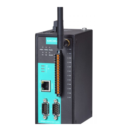
Hardware Introduction As shown in the following figures, the NPort IA5000A-I/O Series has two Ethernet RJ45 LAN ports, and the NPort IAW5000A-I/O Series has one Ethernet RJ45 LAN port and one antenna for WiFi (IEEE 802.11 standards) signal communication, supporting 2.4GHz and 5 GHz frequencies. Both series are equipped with four DIs and two DOs for data acquisition applications. -
Page 3: Nport Ia5000A-I/O Series
DI/DO channels differ. NPort IAW5000A-I/O Series The mechanical design of the NPort IAW5150A and the NPort IAW5250A is mostly identical; only the number of serial ports and number of DI/DO channels differ. -
Page 4: Led Indicators
LED Indicators Name Color Function PWR 1, Green Power is being supplied to power input PWR1, PWR 2 PWR2. Ready Steady on Power is on, and the NPort is booting up. Blinking Indicates an IP conflict, or the DHCP or BOOTP server did not respond properly, or a relay output occurred. -
Page 5: Hardware Installation Procedure
Hardware Installation Procedure STEP 1: After unpacking the unit, connect the power supply to the unit. STEP 2: Use an Ethernet cable to connect the unit to the network. STEP 3: Connect your device to the desired port on the unit. STEP 4: Place or mount the unit. - Page 6 Do not drive the screws in all the way—leave a space of about 2 mm to allow room for sliding the wall-mounting panel between the wall and the screws. NOTE Test the screw head and shank size by inserting the screws into one of the keyhole-shaped apertures of the wall-mounting plates before they are fixed to the wall.
-
Page 7: Software Installation Information
LAN for NPort units, the Device Search Utility will display the IP address of each unit. NOTE (For the NPort IAW5000A-I/O Series) Ethernet Bridge Disabled (default): Only one network interface can be active at a time. If the Ethernet link is active, the WLAN will be inactive. -
Page 8: Pin Assignments
Open the web console to make the configuration changes as follows: STEP 1: Open your web browser. STEP 2: In the address bar, enter the default IP address (for the NPort IA5000A-I/O Series, it is 192.168.127.254; for the NPort IAW5000A-I/O Series, it is 192.168.126.254) STEP 3: The web server will ask for the username and password before you log in. -
Page 9: Specifications
DI/DO Pinouts Digital Digital Digital Digital Digital Digital Output Output Ground Input Input Input Input Common Ground Specifications Power Input 12 to 48 VDC Power Consumption NPort IA5000A-I/O: 300 mA @ 12 V NPort IAW5000A-I/O: 300 mA @ 12 V Operating Temperature Standard models: 0 to 60°C (32 to 140°F) - Page 10 ATTENTION This equipment is intended to be used in Restricted Access Location. WARNING: HOT SURFACE. DO NOT TOUCH! Before touching the surface, pay special attention and take the necessary protection measures. - 10 -...
Need help?
Do you have a question about the NPort IAW5000A-I/O Series and is the answer not in the manual?
Questions and answers