SmartWitness KP1S User Manual
3g/wifi enabled telematics
camera for commercial vehicles
Hide thumbs
Also See for KP1S:
- Installation manual (10 pages) ,
- Installation manual (12 pages) ,
- Installation manual (12 pages)
Table of Contents
Advertisement
Quick Links
Download this manual
See also:
Installation Manual
Advertisement
Table of Contents

Subscribe to Our Youtube Channel
Related Manuals for SmartWitness KP1S


Summary of Contents for SmartWitness KP1S
- Page 1 3G/WiFi Enabled Telematics Camera for Commercial Vehicles KP1S User Guide v1.1...
-
Page 2: Table Of Contents
Table of Contents GPS Reception ................1. Overview ................. Contents ................2. Installation ................3. Basic Operation ..............Automatic Start ..............LED Operation at Start-up ..........G-Sensor Calibration ............Recording Modes ............Communication ............... Over Speed ..............SD Card Initialization ............Inserting The SD Card ............. - Page 3 7. Notification Email Templates ............ 65 Alert Message ............... 65 Event Notification ..............66 Daily Report ................67 8. Email Alerts ................68 Emailing KP1S ................ 68 Request Original Data ............Request System Info ............Request Preview ..............Remote Configure ..............70 9.
- Page 4 CONTINUED... Table of Contents 10. Recording Storage Times ............Continuous Mode ..............Event Mode ................. Dual Mode ……………............. 11. Technical Specs ..............Appendix ..................Firmware Upgrade ..............Optional Accessories - Power Adaptor (INT1-S)....Optional Accessories - Junction Box (INT2)......Optional Accessories - Cigarette Power ....... Optional Accessories - LCD Monitor …………………………………...
- Page 5 SAFETY ADVICE Table of Contents...
-
Page 6: Gps Reception
4) If you are using a receiver connected by a cable, electrical interference can be avoided by simply changing the location of the KP1S installation. 5) On heavily overcast or cloudy days, if the vehicle is in a covered location such as under a bridge or raised roadway, in a tunnel, an underground roadway or parking area, inside a building or surrounded by high-rise buildings. -
Page 7: Overview
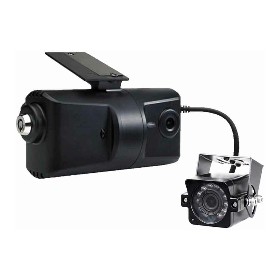
1. OVERVIEW The KP1S is the world’s most advanced incident camera with powerful 3G/WiFi video transmission, GPS location tracking and telematics data. The KP1S also features an optional second camera to help provide a comprehensive view of any incident and keep an eye on valuable cargo. - Page 8 Front Adjustable Bracket Lens (170° Wide Angle Lens) Locking Cover Side SD Card Slot 2 (Slave SD) SD Card Slot 1 (Master SD) USB Interface (For WiFi Dongle) Molded Cable Interface...
- Page 9 (Wireless Status) (Record Error) Speed) Status) Bracket KP1S features a new, easily adjustable bracket designed to give you the ideal viewing angle. To adjust the bracket, follow the steps below. Remove the locking case using the key and turning anti-clockwise.
- Page 10 Then, pinch the red and black clips and then pull the case away from KP1S. Black clip in identical position on the reverse Adjust the angle of the bracket to the desired angle and slide in to lock in place.
- Page 11 Cables KP1S comes with 2 cables permanently connected at the side. The thicker cable connects to the power adaptor cable (KP1S-PWK, KP1S-CIG, KP1S- INT1-S, or KP1S-INT2). The second (thinner) cable connects to the second camera. This cable allows both power and video to be carried to the secondary camera. Please note that the second cable provides power to compatible SmartWitness “-S”...
-
Page 12: Contents
Contents 1x KP1S 1x 3M Adhesive Pad and Adhesive Cable Ties 1x Locking Case 2x Keys for Locking Case 1x User Manual... -
Page 13: Installation
Hardware Installation... -
Page 18: Basic Operation
After this, the internal flash memory will be ready to record. PLEASE NOTE Please make sure to turn off the power of the KP1S when inserting or ejecting the SD card and the USB 3G/WiFi dongle. LED Operation at Start-up... -
Page 19: Recording Modes
Event (Shock, Panic, Overspeed, & Alarm inputs) The event recording function will be automatically started by G-sensor, panic button or alarm. You can set the G-sensor parameters for the unit on your PC using KP1S config software. Each event file will contain 20 seconds of footage before, and up to 20 seconds after an incident. -
Page 20: Communication
During communication, the GREEN LED will be on to show you can communicate. The GREEN LED will flash when communication is performed. The dongle will need to be setup with the correct APN settings using the KP1S config software. If there is a communication error, the unit will ‘Beep’ twice. -
Page 21: Over Speed
SD Card Initialization It’s recommended to use the Configuration Tool to initialize a new SD card before using with KP1S. Configuration Tool Software can be downloaded from http://support.smartwitness.com It is recommended to select “No Configuration File” at first initialization. After SD card is initialized, you can set your desired settings and then click “Save”... -
Page 22: Inserting The Sd Card
Inserting SD Card(s) To insert the SD card, turn off the power and check the BLUE LED Light is off. Once the LED light is off, you can safely insert the card. There are 2 SD Card slots for this unit, please insert the first SD card into SD card slot 1. -
Page 23: Inserting 3G/Wifi Usb Modem
Inserting a WiFi USB Modem Turn off the power and then check the BLUE LED light. Once the BLUE LED light is off, insert the 3G/WiFi USB modem. Check with your distributor for a list of compatible USB modems. LED/Buzzer Specification 1. - Page 24 Buzzer KP1S LED Specification...
- Page 25 Item...
-
Page 27: Recording When Power Is Cut
Recording When Power is Cut During continuous recording The continuous video recording will be recorded up to just before the end of the power is turned off. Power Off Continuous Record Record Off During event recording When the power is off and simultaneously an event is triggered there unit will not be on enough time to record the event file. -
Page 28: Software Installation
3. Software Installation Configuration Tool Before using KP1S, you will need to install both the configuration software and the analysis software to adjust KP1S settings. If you do not have the software you can download it from http://support.smartwitness.com To install the configuration software, follow the steps below. -
Page 29: Analysis Software
7. To finish installation, click the ‘Install’ button. Then, open the software by double clicking the shortcut icon or going to the folder in your documents. Analysis Software To install KP1S Analysis Software, follow the steps below. If you do not have the software you can download it from http://support.smartwitness.com 1. - Page 30 5. Select a destination to save the software to and click ‘Next’. 6. You can set the software to create shortcuts in both the Start Menu and the Desktop, as shown above. 7. To complete the setup, click the ‘Finish’ button. When installed, double click the shortcut icon to open the software.
-
Page 31: Configuration Software
5. Configuration Software Before using KP1S, you will need to open the configuration software to initialize the SD card, configure settings on the unit such as telematics and resolution etc. Before loading the configuration software, insert your SD card into the computer using an SD card Reader. -
Page 32: Device Settings
Device Settings PLEASE NOTE After you make any changes to the configuration options, you must apply the settings to the SD card by clicking “Save” and selecting the SD card... - Page 33 • Type: Choose the connection source: 1. Standard: Bare Wire (KP1S-PWK) or Cigar Power 2. KP1S-INT1: Basic Power Adaptor (No longer available as of May 2015) 3. KP1S-INT1-S: Basic Power Adaptor with delay power shutdown • When INT1-S is selected, a new option will appear to set the delay shut-off time.
- Page 34 Custom Adjust each individual axis of the sensor. • Threshold: Sensitivity difference between the average G-sensor value per second and your set G-sensor value. • Hertz: Set your threshold limit (1~20). If you chose 5, for example, then if the X, Y or Z value is exceeded 5 times within 1 second, the alarm will be triggered.
-
Page 35: Record Settings
Alarm • Beep: Turn the audible camera alarm On or Off. Record Settings Main Camera Resolution (1280x720) (640x480) QVGA (320x240) Camera Resolution (720x480) (720x240) (352x240) - Page 36 Recording Modes -Continuous - Event -Dual Mode: 1fps continuous recording + Event recording (adjust the ‘FPS’ from 1fps to 30fps). Available FPS & Max FPS per Resolution - Single camera mode (Main camera only). Resolution HD (720P) 1280x720 640x480 QVGA 320x240...
- Page 37 Two Camera Mode (Main Camera + 2 Camera) Main Camera Camera Resolution Resolution HD (720P) 1280x720 720x480 HD (720P) 720x240 1280x720 HD (720P) 352x240 1280x720 (720x480) (640x480) QVGA (720x480) (320x240)
-
Page 38: Event Settings
1. When using a standard power cable, you can set the unit to record when triggered by the G-Sensor, Panic Button and/or GPS Speed Limit. 2. When using a KP1S-INT1-S cable, you can also add an alarm output to the above settings. -
Page 39: Information Settings
3. When using a KP1S-INT2 cable, you can also add an alarm and signal to the standard cable settings (Shown Below). Information Settings This option allows you to adjust the Time Zone, GPS Time Synchronization, set your Vehicle ID and also the Driver ID. Click “Retrieve time settings from my PC” button to... -
Page 40: Connectivity Settings
KP1S generated email. Connectivity Settings Enable the 3G or WiFi function on KP1S and adjust the settings for use, i.e. password, User ID, Authentication etc. Please refer to the Cellular Sim provider for these settings. - Page 41 Account Settings In account settings, you can set an email account for KP1S for when you need to email commands. This account is also the email account KP1S will send emails from. Set email address, email ID and Password. Contact your I.T. administrator or your email service provider for the Email setup details such as use SSL, SMTP &...
-
Page 42: Server Settings
Server Settings This option allows you to send KP1S data directly to a server (DMS Server software or integration with Telematics software required). For server setup details, please contact your local distributor or open a support ticket at support.smartwitness.com... -
Page 43: Analysis Software
6. Analysis Software Insert the KP1S SD card and locate the software folder, now install the Analysis software, once installed you can double click on the desktop icon. The main screen will then be displayed as follows: Control Buttons Signal & Alarm... -
Page 44: Playback
Insert the SD Card to your PC. Make sure that the SD Card is properly recognized. After confirming that SD card is recognized correctly in the PC, open the KP1S analysis software and click the “Select SD Card” button. Then, select the correct SD card from... -
Page 45: Open Files
Then, select an SD card and the click the ‘Open SD Card’ button. The list of data tab “continuous” and “event” is displayed on the right side of the screen. The recorded data is displayed under each tab, as shown below: The Playback file list can be separated from the main screen and you can hide it or change the position. -
Page 46: Drive Data
Drive Data KP1S can record not only video and audio, GPS information, speed but also vehicle information like the alarm, G-Sensor, brake, speed Pulse and RPM together (INT-2 power adaptor is required for Speed Pulse & RPM) The recorded information can be Analyzed and played through the KP1S Analysis software. -
Page 47: Analyze Drive Data
Analyze Drive Data During the viewing, click the Analyze Drive data button to view the below Analyze Drive Data screen. From the calendar in the bottom right corner, choose the date you wish to inspect among the dates highlighted in blue. Dates that are not highlighted in blue, do not have the relevant data. - Page 48 A summary of information can be found on the top of the window including; vehicle ID, user ID, total duration and total distance. In addition you can Analyze the number of over-accelerations, over-decelerations, sharp turns, over-speeding, over-RPMs (INT-2 required) that exceeded the pre-set limit. Top Graph The top graph shows the speed (red) and RPM (grey) and below are three indicator bars that show driving patterns.
-
Page 49: Analysis Criteria Settings
Analysis Criteria Settings This option allows you to adjust the change the analysis criteria settings. To access this menu, go to ‘settings’ click ‘analysis criteria settings’ and you will be presented with the following screen. - Page 50 Acceleration/Deceleration This sets the criteria for excessive acceleration and deceleration. This is measured in G-force, so if acceleration or deceleration exceeds the G-force limit, it will be counted as excessive. Speed Limit This option allows you to set the criteria for excessive speeding. You can set the value limits between 0-999km/h.
-
Page 51: Grading Criteria Setting
Grading Criteria Setting The criteria for grading driver’s safety and eco-score can be set in these settings. The safety and eco-grading criteria have 7 and 8 separate components respectively. A weighted average of these component scored are used to determine an overall score. Grading for each criteria is set to 4 levels (A,B,C &... - Page 52 Sudden Acceleration Count This option sets the grading criteria the amount of times there is a sudden acceleration per hour. The assessment of this criteria is based on the (acceleration/ deceleration). For example, if a driver drove for 8 hours in one day and had 4 sudden accelerations during that time, their score for that criteria will be 0.5 and based on the settings in the image on the previous page, they would be graded as B.
- Page 53 Average Speed (kmh/mph) This option sets the grading criteria for speeding and calculates the average speed the driver drove, relative to the speed limit. The value can be set from 0-999km/h. The assessment of this criteria is based on the speed limit option in the ‘Analysis Criteria Setting’.
-
Page 54: Grading Method
Once the grading criteria settings has been adjusted and saved, it can be exported into an ‘.ini’ file and then imported into another version of the analysis software. This means that you can set each KP1S quicker than manually adjusting the settings in each version of the software. - Page 55 Grading & Scores: Each grade is assigned a score; A=100, B=80, C=70, D=60, F=50. With this score, the safety and eco-scores are assessed by a weighted average of the relevant criteria scores. The total score is an average of the safety and eco scores. Below is an example of how scores can be calculated for each criteria.
-
Page 56: Graph Display Setting
Graph Display Settings The results of the driver analysis can be shown on a graph. To adjust the graph display, click on the ‘Graph Display Settings’ option. Max Speed: Set the graph’s upper speed limit (0-999 km/h) Max G-Sensor: Set the graph’s upper G-Sensor limit, by selecting a value from the drop down menu (+-1G, +-2G, +-3G) Max RPM: Set the graph’s upper RPM limit (0-9999) Zoom Window Display Time: Set the time scale for the graph to be in zoom mode... -
Page 57: Tracking Map
If the map is not displayed, make sure that the PC is connected to the internet correctly. The KP1S Analysis Software is composed of a main screen, drive data screen, drive data analysis screen and the tracking screen. These screens can be displayed independently and their location and size changed to improve the use and management of data. -
Page 58: Event Search
Event Search With the KP1S, searching and finding the data is made easy. Utilizing supplementary data such as g-sensor, signals, alarms, speed, and RPM, you can find incidents and events quicker than monitoring the vast amounts of video and audio recordings. -
Page 59: Privacy Settings
Privacy Masking Settings KP1S allows you to set the mosaic area on each channel for privacy protection. When backing up the data as a JPG or AVI format and playing in the Viewer software, you are able to make a mosaic processing on the area you have set. -
Page 60: Save As Jpg
Choose the folder you want to save the image to and click ‘start’. The file will be saved in the default folder of “My Documents\SmartWitness\KP1S\JPG” if you do not specify a Folder. If you check “Privacy Masking”, the image will include the blurs. -
Page 61: Save As Avi
Choose the folder you wish to save the AVI file and type a file name. (The default folder is “My Documents\SmartWitness\KP1S\AVI” and the default name is the date and time.) A video of each camera will be made into an AVI file. -
Page 62: Print Image
Print Image You can print selected images with accompanying information for reporting purposes. To do this, when playing the video press the ‘Print Image button’ (Shown below). Check all camera images you wish to include in the report. Then, type the title of the report and any comments about the situation or other reminders. -
Page 63: Backup
You can back up the recorded data on your PC or other data storage media. KP1S offers an option to store data by type to ease management of data. You can also input additional data such as Vehicle ID, Driver ID, title, and comments to help in administration. -
Page 64: Backup List
Backup List You can use the data backup list to play data files easier that have been backed up. To do this, click the ‘Backup List’ button (below). Choose the folder where the backup files are at the bottom of the screen. (It will automatically show the last folder that was accessed.) Then, select the report type by scrolling down the options. -
Page 65: Software Settings
You can use the data backup list to play data files easier that have been backed up. To do this, click the ‘Backup List’ button (below). Click the ‘Set Password’ button. Password for the KP1S Analysis Software can be set with any number between 1000-9999. -
Page 66: About
About You can check the version information of the KP1S Analysis software. Click the ‘About’ button to see the below pop up. Here, you can check the software version and KP1S firmware version number. For updates please check with your supplier/distributor. -
Page 67: Notification Email Templates
7. Notification Email Templates Alert Message Email from KP1S The KP1S will send an email notification to alert you when an incident happens. Below explains the content and subject header of the emails. Email Subject: ALERT > Vehicle ID > Date-Time For Example: ALERT >... -
Page 68: Event Notification
Event Notification Email from KP1S The KP1S will send an email notification when an incident happens. Below explains the content and subject header of the emails. Email Subject: ID > Vehicle ID > Event Type > Date-Time For Example: ID > Y122 VVE > G > 16/04/2014-17:39:17... -
Page 69: Daily Report
Daily Report Email from KP1S Email Subject: ID>Vehicle ID>DR>Date-Time For example: ID>Y122 VVE>DR>2014/04/16-17:39:17 Email Body: 2014/04/15> 9:39:13 > G 2014/04/15> 10:39:13 > P 2014/04/15> 11:39:13 > A Total: 3... -
Page 70: Email Alerts
8. Email Alerts Emailing the KP1S You can email the KP1S to receive alerts from the camera for alarm triggers, video data and speeding etc. The KP1S will email details of the data requested, however not as detailed as the event notifications. -
Page 71: Request System Info
Send an Email to KP1S Email Subject: I_ >_Admin Password For example: I_ >_55555 When you have sent the email request, the KP1S will send the following email back to the registered email address. Email Subject: INFO>Vehicle ID For example: INFO>Y122 VVE... -
Page 72: Remote Configure
To send the ‘setting.ini file’ use the config tool to adjust the settings to your requirements and click the ‘save’ button and then ‘select folder’ button. This will create the file that you can attach on the email to the KP1S and apply these settings to the unit. - Page 73 When you have sent the email request on the previous page, the KP1S will send the following email back to the registered email address. Email Subject: S_>_Admin Password: REQUEST TITLE For example: S_>_555555:>Remote Configure Email Body: INVALID PASSWORD INVALID REQUEST INVALID ARGUMENT: Without setting .ini file or misspelling...
-
Page 74: Sms Templates
9. SMS Templates SMS: Alert Message SMS from KP1S SMS Body: ALERT > Y122 VVE > 2014/04/16-17.39.17 / IGNITION ON ALERT > Y122 VVE > 2014/04/16-17.39.17 / SPEED LIMIT EXCEEDED ALERT > Y122 VVE > 2014/04/16-17.39.17 / SD CARD1 ERROR ALERT >... -
Page 75: Continuous Mode
10. Recording Time Table Continuous Mode SD Card (in Hours) Quality Resolution 16GB 32GB... - Page 76 *This is a guideline only. Actual results may very depending on a variety of factors. Limitation of the total file number In Event Record Mode: 1 camera recording: The number of files is limited to a maximum of 3,000. 2 camera recording: The number of files is limited to a maximum of 2,000.
-
Page 77: Event Mode
In Continuous Record Mode: Regardless of the number of cameras, the maximum recording number is 1,000. At the Dual (Continuous + Event) Record mode 1 camera recording, maximum recording number (Event folder: 2,000, Normal folder: 1000) 2 camera recording, maximum recording number (Event folder: 1,500, Normal folder: 1000) PLEASE NOTE If the number or recorded files will exceed the maximum (1,000), then they will be... -
Page 78: Dual Mode
11. SPECIFICATIONS Dual Recording Mode Camera 1 Camera 2 SD Card Record Resolution Quality Quality Resolution Folder 16GB 32GB Normal Hours Hours Hours Hours Super Super 1480 Event Events Events Events Events Normal Hours Hours Hours Hours High High 640x480 720x480 1500 Event... - Page 79 Super Capacitor Enables the recording of the last file before shut down PC Software KP1S Config Software / KP1S Analysis Software Cigarette Jack: Input - DC 12V/24V 2A, Output: DC 5V 3A Power Input Power Adaptor: Input - DC12/24V, Output: DC 5V 3A...
-
Page 80: Appendix 1
3. Make a folder called program” on the SD Card as shown below. 4. Copy the “KP1S_2.2.X.bin” file into the SD card’s ‘program’ folder. 5. Make sure KP1S is turned off and insert the prepared SD card into KP1S SD slot 1 and turn on the power. -
Page 81: Optional Accessories
Appendix 2 Optional Accessories Power Adaptor: KP1S-INT1-S Input Voltage DC 12V / 30V 2000mA Output Voltage DC 5V 3000mA Operation Temp. -20°C ~ +60°C... - Page 82 Appendix 3 Junction Box: KP1S-INT2 Optional Accessories...
- Page 83 Junction Box DIP Switch cont’d...
-
Page 84: Optional Accessories - Cigarette Power
Appendix 4 Optional Accessories Cigarette Power: KP1S-CIGAR... - Page 85 Appendix 5 LCD Monitor with Rear Camera & KP1S...
- Page 86 Technical Support For Technical Support, please contact your local distributor. Or go online: http://support.smartwitness.com Limited Warranty This product is supplied with a 2 year warranty. The Warranty excludes products that have been misused, (including accidental damage) and damage caused by normal wear and tear.
- Page 87 NOTES...
- Page 88 ©2016 SmartWitness PLC www.smartwitness.com...
Need help?
Do you have a question about the KP1S and is the answer not in the manual?
Questions and answers