Table of Contents
Advertisement
Quick Links
S i 5 3 5 0 / 5 1 2 0 - Q F N E
Description
The Si535x-B20QFN-EVB is used for evaluating the
Si5350/51 any-frequency, 0.0025–200 MHz CMOS
clock generator + VCXO.
Functional Block Diagram
USB
Connector
Rev. 0.3 7/15
S i 5 3 5 x - B 2 0 Q F N - E V B
V A L U A T I O N
Features
Vreg*
Jumper Selectable Vreg
1.8 V (VDDO only) / 2.5 V / 3.3 V
VDD
XTAL
CLKIN
Si5350/51
V
C
I2C
Status
LEDs
MCU
Reset
Switch
Copyright © 2015 by Silicon Laboratories
B
U
O A R D
S E R
Fully-powered from a single USB port
Onboard 27 MHz crystal for asynchronous operation
SMA and test point hook for interfacing to an
external clock reference
Jumper-selectable VDD and VDDOx allows device
to operate at 1.8 (VDDO only), 2.5, or 3.3 V
Voltage supply jumpers provide easy access for use
with external supplies
Vreg*
VReg
VReg
VReg
VDDO0
CLK0
CLK1
VDDO1
CLK2
CLK3
VDDO2
CLK4
CLK5
VDDO3
CLK6
CLK7
'
G
S
UI DE
Si535x-B20QFN-EVB
Advertisement
Table of Contents

Related Manuals for Silicon Laboratories Si5350/51-B20QFN-EVB


Summary of Contents for Silicon Laboratories Si5350/51-B20QFN-EVB
- Page 1 1.8 V (VDDO only) / 2.5 V / 3.3 V VDDO0 CLK0 CLK1 XTAL VDDO1 CLK2 CLK3 CLKIN Si5350/51 VDDO2 CLK4 CLK5 VDDO3 CLK6 CLK7 Status LEDs Reset Switch Connector Rev. 0.3 7/15 Copyright © 2015 by Silicon Laboratories Si535x-B20QFN-EVB...
-
Page 2: Functional Block Diagram
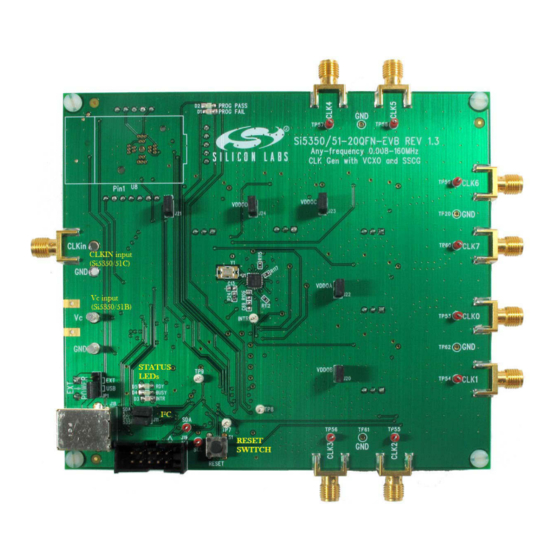
Si535x-B20QFN-EVB 1. Functional Block Diagram Figures 1 and 2 highlight the main features of the EVB. The onboard MCU is responsible for programming the Si535x timing IC, measuring the device's current consumption reported in the ClockBuilder™ Desktop, managing power, and controlling status LEDs. VDD and VDDO jumpers allow the option of choosing between 1.8 (VDDO only), 2.5, and 3.3 V or powering the device with external supplies (see Section “2. - Page 3 Si535x-B20QFN-EVB Figure 2. EVB Features (Back) Rev. 0.3...
-
Page 4: Status Leds
Si535x-B20QFN-EVB 2. Jumpers The following jumpers are available on the evaluation board: VDD—Connects the Si5350/51 pin to the VDD voltage regulator (normally installed). VDD VOLT_SEL—Allows user to select a VDD voltage of 2.5 V or 3.3 V (default 3.3 V). ... -
Page 5: Software Guide
3. After the installation is complete, click on Start Programs Silicon Laboratories ClockBuilder Desktop Software. Select one of the items in the menu including the User Guide to get more details on how to run the software. -
Page 6: Si535X-B20Qfn-Evb Schematics
Si535x-B20QFN-EVB 7. Si535x-B20QFN-EVB Schematics Rev. 0.3... - Page 7 Si535x-B20QFN-EVB Rev. 0.3...
- Page 8 Si535x-B20QFN-EVB Rev. 0.3...
-
Page 9: Bill Of Materials
Si535x-B20QFN-EVB 8. Bill of Materials Table 1. Si535x Bill of Materials Item Qty Reference Value Manufacturer Manufacturer Part Number C2,C5,C7,C8,C9 0.47 µF Venkel C0402X5R100-474K Venkel C0603X7R101-102K C17,C18,C20,C21,C22,C23, 0.1 µF Venkel C0402X7R100-104K C26,C27,C31,C32,C33,C35 C19,C24,C42,C45,C48,C54, 4.7 µF Venkel C1206X7R100-475M C25,C30 1 µF Venkel C1206X7R250-105K C28,C29,C34,C41,C43,C46,... - Page 10 Si535x-B20QFN-EVB Table 1. Si535x Bill of Materials (Continued) Item Qty Reference Value Manufacturer Manufacturer Part Number R36,R37,R38,R42,R44,R49, Venkel CR0402-16W-102J R50,R55 R41,R110,R111,R112,R113, Venkel CR0402-16W-000 R114,R115,R116,R117 R43,R46,R47 Venkel CR0402-16W-221J R45,R48,R60,R61 1.02K Venkel TFCR0402-16W-E-1021B Venkel TFCR0402-16W-E-4120B R72,R73,R74,R90,R91 Venkel CR2512-1W-20R0D R75,R76,R78,R92,R95,R97, Venkel CR0603-16W-1002F R106 R77,R79,R80,R93,R94,R96 100K Venkel...
-
Page 11: Approved Crystals
Si535x-B20QFN-EVB 9. Approved Crystals The crystals listed in Table 2 have been approved for use with the Si5350/51 family of devices. Note that this device has on-chip load capacitors that can be configured for 0, 6, 8, and 10 pF. For crystals with any other rated load capacitance, external capacitors may be required to achieve the best absolute accuracy. - Page 12 The products must not be used within any Life Support System without the specific written consent of Silicon Laboratories. A "Life Support System" is any product or system intended to support or sustain life and/or health, which, if it fails, can be reasonably expected to result in significant personal injury or death.
Need help?
Do you have a question about the Si5350/51-B20QFN-EVB and is the answer not in the manual?
Questions and answers