Table of Contents
Advertisement
Quick Links
Si5342 E
VALUATION
Description
The Si5342-EVB is used for evaluating the Si5342
Any-Frequency, Any-Output, Jitter-Attenuating Clock
Multiplier. The Si5342 combines 4th generation DSPLL
and Multisynth
technologies to enable any-frequency
clock generation for applications that require the highest
level of jitter performance. The Si5342-EVB can be
controlled and configured using the ClockBuilder Pro
(CB Pro
) software tool.
Rev. 1.0 5/15
B
U
OARD
EVB Features
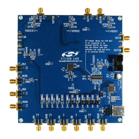
Figure 1. Si5342 Evaluation Board
Copyright © 2015 by Silicon Laboratories
S i 5 3 4 2 - E V B
'
G
SER
S
U I D E
Powered from USB port or external power supply.
Onboard 48 MHz XTAL or Reference SMA Inputs
allow holdover mode of operation on the Si5342.
CBPro
GUI programmable V
device to operate from 3.3, 2.5, or 1.8 V.
CBPro
GUI programmable V
each of the 4 outputs to have its own power supply
voltage selectable from 3.3, 2.5, or 1.8 V.
CBPro
GUI allows control and measurement of
voltage, current, and power of V
supplies.
Status LEDs for power supplies and control/status
signals of Si5342.
SMA connectors for input clocks, output clocks, and
optional external timing reference clock.
supply allows
DD
supplies allow
DDO
and all 4 V
DD
DDO
Si5342-EVB
Advertisement
Table of Contents

Related Manuals for Silicon Laboratories Si5342-EVB


Summary of Contents for Silicon Laboratories Si5342-EVB
- Page 1 ’ VALUATION OARD U I D E Description EVB Features The Si5342-EVB is used for evaluating the Si5342 Powered from USB port or external power supply. Any-Frequency, Any-Output, Jitter-Attenuating Clock Onboard 48 MHz XTAL or Reference SMA Inputs Multiplier.
- Page 2 1. Si5342-EVB Functional Block Diagram Below is a functional block diagram of the Si5342-EVB. This EVB can be connected to a PC via the main USB connector for programming, control, and monitoring. See section “3. Quick Start” or section “9. Installing ClockBuilderPro (CBPro) Desktop Software”...
-
Page 3: Quick Start
1. Install ClockBuilderPro desktop software from http://www.silabs.com/CBPro. 2. Connect a USB cable from Si5342-EVB to the PC where the software was installed. 3. Leave the jumpers as installed from the factory, and launch the ClockBuilderPro software. 4. You can use ClockBuilderPro to create, download, and run a frequency plan on the Si5342-EVB. -
Page 4: Jumper Defaults
Si5342-EVB 4. Jumper Defaults Si5342 EVB Jumper Defaults I = Installed I = Installed Location Type Location Type 0 = Open 0 = Open 2 pin 2 pin 2 pin 2 pin 3 pin 1 to 2 (USB) JP13 2 pin 5x2 Hdr All 5 installed Refer to the Si5342 EVB schematics for the functionality associated with each jumper. -
Page 5: Status Leds
Si5342-EVB 5. Status LEDs Si5342 EVB Status LEDs Location Silkscreen Color Status Function Indication INTRB Blue MCU INTR (Interrupt) active LOLB Blue MCU INTR (Interrupt) active LOS0B* Blue IN0 Loss of Signal indicator LOS1B* Blue IN0 Loss of Signal indicator LOS3B* Blue IN0 Loss of Signal indicator... -
Page 6: Clock Input Circuits (Inx/Inxb)
Figure 5 below. The output signal will have no DC bias. If DC coupling is required, the AC coupling capacitors can be replaced with a resistor of appropriate value. The Si5342-EVB provides an L-network at OUT0/OUT0B output pins for optional output termination resistors. Note that components with schematic “NI”... - Page 7 Si5342-EVB 8. External Reference Clock Input Circuit (XA/XB) The Si5342 EVB supports either XTAL or external reference clock on XA/XB. By default, the XTAL is populated. If a reference clock is required for testing, remove Y1 and place C93/C94. A low-jitter reference clock can then be applied to J25/J26.
- Page 8 Although additional power (besides the power supplied by the host PC’s USB port) is not needed for most configurations, two additional +5 VDC power supplies (MAIN and AUX) can be connected to J33 and J34 (located on the bottom of the board, near the USB connector). Refer to the Si5342-EVB schematic for details. Rev. 1.0...
- Page 9 Si5342-EVB 10.3. Overview of ClockBuilderPro Applications The ClockBuilderPro installer will install two main applications: Figure 8. Application #1: ClockbuilderPro Wizard Use the CBPro Wizard to: Create a new design Review or edit an existing design Export: create in-system programming Figure 9.
- Page 10 Si5342-EVB 10.4. Common ClockBuilderPro Work Flow Scenarios There are three common workflow scenarios when using CBPro and the Si5342 EVB. These workflow scenarios are: Workflow Scenario #1: Testing a Silicon Labs-Created Default Configuration Workflow Scenario #2: Modifying the Default Silicon Labs-Created Device Configuration ...
- Page 11 Si5342-EVB After CBPro writes the default plan to the EVB, click on “Open EVB GUI” as shown below. Figure 14. Open EVB GUI The EVB GUI will appear. Note all power supplies will be set to the values defined in the device’s default CBPro project file created by Silicon Labs, as shown below.
- Page 12 Si5342-EVB the crystal) using appropriate external instrumentation connected to the output clock SMA connectors. To verify the output clocks are toggling at the correct frequency and signal format, click on View Design Report as highlighted below. Figure 17. View Design Report Your configuration’s design report will appear in a new window, as shown below.
- Page 13 Si5342-EVB 10.6. Workflow Scenario #2: Modifying the Default Silicon Labs-Created Device Configuration To modify the “default” configuration using the CBPro Wizard, click on Edit Configuration with Wizard: Figure 19. Edit Configuration with Wizard You will now be taken to the Wizard’s step-by-step menus to allow you to change any of the default plan’s operating configurations.
- Page 14 Si5342-EVB Note you can click on the icon on the lower left hand corner of the menu to confirm if your frequency plan is valid. After making your desired changes, you can click on Write to EVB to update the DUT to reconfigure your device real-time.
- Page 15 Si5342-EVB Locate your CBPro design file (*.slabtimeproj or *.sitproj file).design file in the Windows file browser. Figure 23. Browse to Project File Select Yes when the WRITE DESIGN to EVB popup appears: Figure 24. Write Design to EVB Dialog The progress bar will be launched. Once the new design project file has been written to the device, verify the presence and frequencies of your output clocks and other operating configurations using external instrumentation.
- Page 16 Si5342-EVB 10.8. Exporting the Register Map File for Device Programming by a Host Processor You can also export your configuration to a file format suitable for in-system programming by selecting Export as shown below: Figure 25. Export Register Map File You can now write your device’s complete configuration to file formats suitable for in-system programming.
-
Page 17: Writing A New Frequency Plan Or Device Configuration To Non-Volatile Memory (Otp)
The Si5342 EVB Schematic and Bill of Materials (BOM) can be found online at http://www.silabs.com/products/clocksoscillators/pages/si538x-4x-evb.aspx Note: Please be aware that the Si5342-EVB schematic is in OrCad Capture hierarchical format and not in a typical “flat” sche- matic format. Rev. 1.0... - Page 18 The products must not be used within any Life Support System without the specific written consent of Silicon Laboratories. A "Life Support System" is any product or system intended to support or sustain life and/or health, which, if it fails, can be reasonably expected to result in significant personal injury or death.
Need help?
Do you have a question about the Si5342-EVB and is the answer not in the manual?
Questions and answers