Table of Contents
Advertisement
UG335: Si5395 Evaluation Board User's
Guide
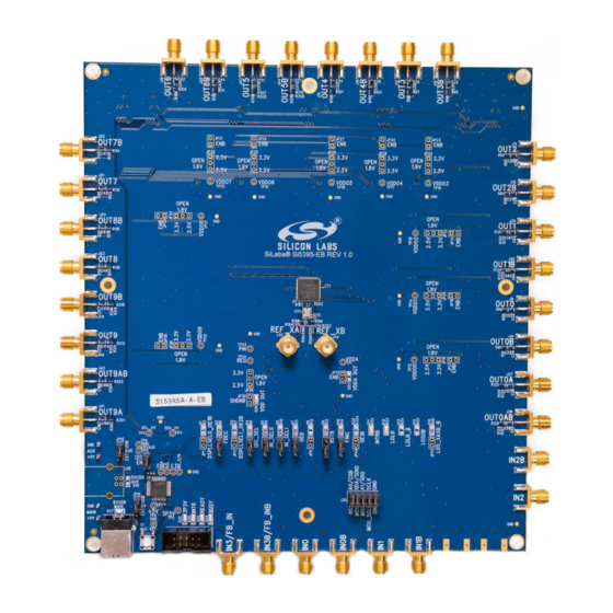
The Si5395 EVB is used for evaluating the Si5395 Any-Frequency, Any-Output, Jitter-
Attenuating Clock Multiplier. There are two different EVBs for the Si5395. There is a
Grade A and a Grade P board. This user guide is intended for both versions of the
Si5395 EVBS. The device grade and revision is distinguished by a white 1 inch x 0.187
inch label installed in the lower left hand corner of the board. In the example below, the
label "SI5395A-A-EB" indicates the evaluation board has been assembled with an
Si5395 device, Grade A, Revision A, installed. (For ordering purposes only, the terms
"EB" and "EVB" refer to the board and the kit, respectively. For the purpose of this docu-
ment, the terms are synonymous in context.)
silabs.com | Building a more connected world.
KEY FEATURES
• Powered from USB port or external power
supply
• Onboard 48 MHz XTAL or Reference SMA
Inputs allow holdover mode of operation on
the Si5395
• CBPro™ GUI programmable VDD supply
allows device to operate from 3.3, 2.5, or
1.8 V
• CBPro GUI programmable VDDO supplies
allow each of the 10 outputs to have its
own power supply voltage selectable from
3.3, 2.5, or 1.8 V
• CBPro GUI-controlled voltage, current, and
power measurements of VDD and all
VDDO supplies
• Status LEDs for power supplies and
control/status signals of Si5395
• SMA connectors for input clocks, output
clocks, and optional external timing
reference clock
Rev. 0.96
Advertisement
Table of Contents

Related Manuals for Silicon Laboratories Si5395


Summary of Contents for Silicon Laboratories Si5395
- Page 1 Grade A and a Grade P board. This user guide is intended for both versions of the Si5395 EVBS. The device grade and revision is distinguished by a white 1 inch x 0.187 • Powered from USB port or external power inch label installed in the lower left hand corner of the board.
-
Page 2: Functional Block Diagram
Functional Block Diagram 1. Functional Block Diagram Below is a functional block diagram of the Si5395 EVB. This evaluation board can be connected to a PC via the main USB connector for programming, control, and monitoring. See 3. Quick Start 10.3 Overview of ClockBuilderPro Applications... -
Page 3: Si5395 Evb Support Documentation And Clockbuilderpro™ Software
UG335: Si5395 Evaluation Board User's Guide Si5395 EVB Support Documentation and ClockBuilderPro™ Software 2. Si5395 EVB Support Documentation and ClockBuilderPro™ Software All Si5395 EVB schematics, BOMs, User’s Guides, and software can be found online at: http://www.silabs.com/products/clocksoscilla- tors/pages/si539x-evb.aspx. silabs.com | Building a more connected world. -
Page 4: Quick Start
3. Leave the jumpers as installed from the factory, and launch the ClockBuilderPro software. 4. You can use ClockBuilderPro to create, download, and run a frequency plan on the Si5395 EVB. 5. For the Si5395 data sheet, go to http://www.silabs.com/timing. -
Page 5: Jumper Defaults
2-pin JP41 2-pin JP21 2-pin 5 x 2 Hdr All 5 installed JP22 2-pin Note: 1. Refer to the Si5395 EVB schematics for the functionality associated with each jumper. silabs.com | Building a more connected world. Rev. 0.96 | 5... -
Page 6: Status Leds
BUSY Green MCU Busy D27, D22, and D26 are illuminated when USB +5 V, Si5395 +3.3 V, and Si5395 VDD supply voltages, respectively, are present. D25, D21, and D24 are status LEDs showing on-board MCU activity. Figure 5.1. Status LEDs silabs.com | Building a more connected world. -
Page 7: External Reference Input (Xa/Xb)
An external reference (XTAL) is used in combination with the internal oscillator to produce an ultra-low-jitter reference clock for the DSPLL and to provide a stable reference for the free-run and holdover modes. The Si5395 EVB can also accommodate an external reference clock instead of a crystal. -
Page 8: Clock Input Circuits (Inx/Inxb)
7. Clock Input Circuits (INx/INxB) The Si5395 EVB has eight SMA connectors (IN0, IN0B – IN3, IN3B) for receiving external clock signals. All input clocks are terminated as shown below. Note that input clocks are ac-coupled and 50 Ω terminated. This represents four differential input clock pairs. Single- ended clocks can be used by appropriately driving one side of the differential pair with a single-ended clock. -
Page 9: Clock Output Circuits (Outx/Outxb)
The Si5395 EVB provides pads for optional output termination resistors and/or low-frequency capacitors. Note that components with the schematic “NI” designation are not normally populated on the Si5395 EVB and provide locations on the PCB for optional dc/ac terminations by the end user. - Page 10 UG335: Si5395 Evaluation Board User's Guide Installing ClockBuilderPro (CBPro) Desktop Software 9. Installing ClockBuilderPro (CBPro) Desktop Software To install the CBOPro software on any Windows 7 (or above) PC, go to http://www.silabs.com/CBPro and download the ClockBuilder- Pro software. Installation instructions and User’s Guide for ClockBuilderPro can be found at the download link shown above.
-
Page 11: Using The Si5395 Evb
UG335: Si5395 Evaluation Board User's Guide Using the Si5395 EVB 10. Using the Si5395 EVB 10.1 Connecting the EVB to Your Host PC Once ClockBuilderPro software is installed, connect to the EVB with a USB cable as shown in the figure below: Figure 10.1. - Page 12 Refer to the Si5395 EVB schematic for details. The Si5395 EVB comes preconfigured with jumpers installed at JP15 and JP16 (pins 1–2 in both cases) in order to select “USB”. These jumpers, together with the components installed, configure the evaluation board to obtain all +5 V power solely through the main USB connector at J37.
- Page 13 • Export: create in-system programming Figure 10.4. Application #2: EVBGUI Use the EVB GUI to: • Download configuration to EVB’s DUT (Si5395) • Control the EVB’s regulators • Monitor voltage, current, and power on the EVB silabs.com | Building a more connected world.
- Page 14 Using the Si5395 EVB 10.4 Common ClockBuilderPro Workflow Scenarios There are three common workflow scenarios when using CBPro and the Si5395 EVB. These workflow scenarios are: • Workflow Scenario 1: Testing a Silicon Labs-Created Default Configuration • Workflow Scenario 2: Modifying the Default Silicon Labs-Created Device Configuration •...
- Page 15 Figure 10.7. Write Design to EVB Dialog Select “Yes” to write the default plan to the Si5395 device mounted on your EVB. This ensures the device is completely reconfigured per the Silicon Labs default plan for the DUT type mounted on the EVB.
- Page 16 UG335: Si5395 Evaluation Board User's Guide Using the Si5395 EVB Figure 10.10. EVB GUI Window silabs.com | Building a more connected world. Rev. 0.96 | 16...
- Page 17 UG335: Si5395 Evaluation Board User's Guide Using the Si5395 EVB 10.5.1 Verify Free-Run Mode Operation Assuming no external clocks have been connected to the INPUT CLOCK differential SMA connectors (labeled “INx/INxB”) located around the perimeter of the EVB, the DUT should now be operating in free-run mode, as the DUT will be locked to the crystal in this case.
- Page 18 UG335: Si5395 Evaluation Board User's Guide Using the Si5395 EVB Figure 10.12. View Design Report Your configuration’s design report will appear in a new window, as shown below. Compare the observed output clocks to the frequen- cies and formats noted in your default project’s Design Report.
- Page 19 UG335: Si5395 Evaluation Board User's Guide Using the Si5395 EVB Figure 10.13. Design Report Window 10.5.2 Verify Locked Mode Operation Assuming you connect the correct input clocks to the EVB (as noted in the Design Report shown above), the DUT on your EVB will run in “locked”...
- Page 20 UG335: Si5395 Evaluation Board User's Guide Using the Si5395 EVB 10.6 Workflow Scenario 2: Modifying the Default Silicon Labs-Created Device Configuration To modify the “default” configuration using the CBPro Wizard, click on the links below under “Edit Configuration with Wizard”.
- Page 21 UG335: Si5395 Evaluation Board User's Guide Using the Si5395 EVB Figure 10.15. Design Wizard Note that you can click on the icon in the lower left hand corner of the menu to confirm that your frequency plan is valid. After making your desired changes, click on Write to EVB to update the DUT and reconfigure your device real-time.
- Page 22 UG335: Si5395 Evaluation Board User's Guide Using the Si5395 EVB 10.7 Workflow Scenario 3: Testing a User-Created Device Configuration To test a previously created user configuration, open the CBPro Wizard by clicking the icon on your desktop and selecting Open Design Project File.
- Page 23 UG335: Si5395 Evaluation Board User's Guide Using the Si5395 EVB Select "Yes" when the WRITE DESIGN to EVB popup appears: Figure 10.19. Write Design to EVB Dialog The progress bar will be launched. Once the new design project file has been written to the device, verify the presence and frequencies of your output clocks and other operating configurations using external instrumentation.
- Page 24 UG335: Si5395 Evaluation Board User's Guide Using the Si5395 EVB 10.8 Exporting the Register Map File for Device Programming by a Host Processor You can also export your configuration to a file format suitable for in-system programming by selecting Export as shown below: Figure 10.20.
-
Page 25: Writing A New Frequency Plan Or Device Configuration To Non-Volatile Memory (Otp)
Note: Writing to the device non-volatile memory (OTP) is NOT the same as writing a configuration into the Si5395 using ClockBuilder- Pro on the Si5395 EVB. Writing a configuration into the EVB from ClockBuilderPro is done using Si5395 RAM space and can be done a virtually unlimited numbers of times. -
Page 26: Serial Device Communications
The MCU onboard the Si5395 EVB communicates with the Si5395 device through a 4-wire SPI (Serial Peripheral Interface) link. The MCU is the SPI master and the Si5395 device is the SPI slave. The Si5395 device can also support a 2-wire I... -
Page 27: Si5395 Evb Schematic, Layout, And Bill Of Materials (Bom)
Note: Please be aware that the Si5395 EVB schematic is in OrCad Capture hierarchical format and not in a typical “flat” schematic format. This document supports the evaluation board silkscreened Si5395 EVB for the following configurations as described in the table below. - Page 28 Trademark Information Silicon Laboratories Inc.® , Silicon Laboratories®, Silicon Labs®, SiLabs® and the Silicon Labs logo®, Bluegiga®, Bluegiga Logo®, Clockbuilder®, CMEMS®, DSPLL®, EFM®, EFM32®, EFR, Ember®, Energy Micro, Energy Micro logo and combinations thereof, "the world’s most energy friendly microcontrollers", Ember®, EZLink®, EZRadio®, EZRadioPRO®, Gecko®, ISOmodem®, Micrium, Precision32®, ProSLIC®, Simplicity Studio®, SiPHY®, Telegesis, the Telegesis Logo®, USBXpress®, Zentri, Z-Wave, and others are trademarks or...
Need help?
Do you have a question about the Si5395 and is the answer not in the manual?
Questions and answers