Table of Contents
Advertisement
Quick Links
S i 5 3 4 0 E
V A L U A T I O N
Description
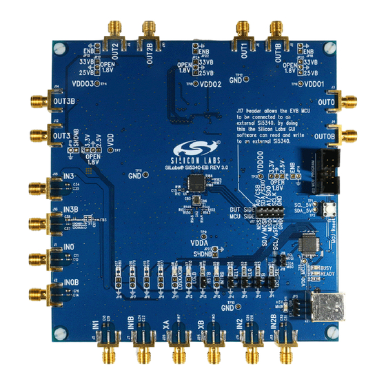
The Si5340-EVB is used for evaluating the Si5340 Low
Jitter Any-Frequency Clock Generator. The Si5340 uses
TM
the patented Multisynth
10 independent clock frequencies each with 0 ppm
synthesis error. The Si5340-EVB has 3 independent
input clocks, an optional feedback input clock for zero
delay mode, and 4 independent output clocks. The
Si5340-EVB can be controlled and configured using the
TM
Clock Builder Pro
(CB Pro
Si5340 Evaluation Board
Rev. 1.0
B
O A R D
technology to generate up to
TM
) software tool.
Copyright © 2015 by Silicon Laboratories
Si5340- EV B
U
'
G
S E R
S
U I D E
Features
Powered from USB port or external power supply
Onboard 48 MHz XTAL allows free-run mode of
operation on the Si5340 or up to 3 input clocks for
synchronous clocking
Feedback clock input for optional zero delay mode
TM
CBPro
GUI-programmable VDD supply allows
device to operate from 3.3, 2.5, or 1.8 V.
CBPro GUI-programmable VDDO supplies allow
each of the 4 outputs to have its own supply voltage
selectable from 3.3, 2.5, or 1.8 V
CBPro GUI-controlled voltage, current, and power
measurements of VDD and all VDDO supplies.
Status LEDs for power supplies and control/status
signals of Si5340
SMA connectors for input and output clocks
Si5340-EVB
Advertisement
Table of Contents

Related Manuals for Silicon Laboratories Si5340-EVB


Summary of Contents for Silicon Laboratories Si5340-EVB
- Page 1 S E R U I D E Description Features The Si5340-EVB is used for evaluating the Si5340 Low Powered from USB port or external power supply Jitter Any-Frequency Clock Generator. The Si5340 uses Onboard 48 MHz XTAL allows free-run mode of ...
-
Page 2: Functional Block Diagram
1. Functional Block Diagram Below is a functional block diagram of the Si5340-EVB. This EVB can be connected to a PC via the main USB connector for programming, control, and monitoring. See Section “3. Quick Start” or Section “9. Installing ClockBuilderPro (CBPro) Desktop Software”... -
Page 3: Quick Start
1. Install ClockBuilderPro™ desktop software: http://www.silabs.com/CBPro 2. Connect a USB cable from the Si5340-EVB to the PC where the software is installed. 3. Leave the jumpers as installed from the factory and launch the ClockBuilderPro™ software. 4. You can use ClockBuilderPro™ to create, download, and run a frequency plan on the Si5340-EVB. -
Page 4: Status Leds
Si 53 40-EV B 5. Status LEDs Si5340 EVB Status LEDs Location Silkscreen Color Status Function Indication INTRB Blue DUT Interrupt LOLB Blue DUT Loss of Lock LOSXAXBB Blue DUT Loss of Reference +5V MAIN Green Main USB +5V present READY Green MCU Ready BUSY... -
Page 5: External Reference Input (Xa/Xb)
DSPLL and for providing a stable reference for the free-run and holdover modes. The Si5340-EVB can also accommodate an external reference clock instead of a crystal. To evaluate the device with a REFCLK, C93 and C94 must be populated and the XTAL removed (see Figure 3 below). The REFCLK can then be applied to J25 and J26. -
Page 6: Clock Output Circuits (Outx/Outxb)
The Si5340-EVB provides pads for optional output termination resistors and/or low frequency capacitors. Note: Components with schematic “NI” designation are not normally populated on the Si5340-EVB and provide locations on the PCB for optional DC/AC terminations by the end user. - Page 7 Si 5 34 0- E V B 10.2. Overview of ClockBuilderPro Applications The ClockBuilderPro™ installer installs two main applications: the ClockBuilderPro Wizard and the EVB GUI. Figure 7. Application #1: ClockBuilderPro Wizard Use the CBPro Wizard to do the following: Create a new design ...
- Page 8 Si 53 40-EV B 10.3. Common ClockBuilderPro Work Flow Scenarios There are three common workflow scenarios when using CBPro and the Si5340 EVB. These workflow scenarios are as follows: Workflow Scenario #1: Testing a Silicon Labs-created default configuration Workflow Scenario #2: Modifying the default Silicon Labs-created device configuration ...
- Page 9 Si 5 34 0- E V B 4. Select Yes to write the default plan to the Si5340 device mounted on your EVB. This ensures the device is completely reconfigured per the Silicon Labs default plan for the DUT type mounted on the EVB. Figure 12.
- Page 10 Si 53 40-EV B Verify Free-Run Mode Operation Assuming no external clocks have been connected to the INPUT CLOCK differential SMA connectors (labeled "INx/INxB") located around the perimeter of the EVB, the DUT should now be operating in free-run mode, as the DUT will be locked to the crystal in this case.
- Page 11 Si 5 34 0- E V B Your configuration's design report appears in a new window, shown in Figure 17. Compare the observed output clocks to the frequencies and formats noted in your default project's Design Report. Figure 17. Design Report Window Rev.
- Page 12 Si 53 40-EV B Verify Locked Mode Operation Assuming you connect the correct input clocks to the EVB (as noted in the Design Report shown above), the DUT on your EVB will be running in "locked" mode. 10.3.2. Workflow Scenario #2: Modifying the Default Silicon Labs-Created Device Configuration To modify the "default"...
- Page 13 Si 5 34 0- E V B Figure 20. Writing Design Status 10.3.3. Workflow Scenario #3: Testing a User-Created Device Configuration 1. To test a previously-created user configuration, open the CBPro Wizard by clicking on the icon on your desktop and then selecting Open Design Project File. Figure 21.
- Page 14 Si 53 40-EV B 3. Select Yes when the Write Design to EVB popup appears. Figure 23. Write Design to EVB Dialog 4. The progress bar is launched. Once the new design project file has been written to the device, verify the presence and frequencies of your output clocks and other operating configurations using external instrumentation.
- Page 15 Si 5 34 0- E V B You can now write your device's complete configuration to file formats suitable for in-system programming. Figure 25. Export Settings Rev. 1.0...
-
Page 16: Writing A New Frequency Plan Or Device Configuration To Non-Volatile Memory (Otp)
Interface) link. The MCU is the SPI master and the Si5340 device is the SPI slave. The Si5340 device can also support a 2-wire I2C serial interface, although the Si5340-EVB does NOT support the I2C mode of operation. SPI mode was chosen for the EVB because of the relatively higher speed transfers supported by SPI vs. I2C. - Page 17 Si 5 34 0- E V B 13. Si5340-EVB Schematic and Bill of Materials (BOM) The Si5340 EVB Schematic and Bill of Materials (BOM) can be found online at: http://www.silabs.com/products/clocksoscillators/pages/si538x-4x-evb.aspx Please be aware the Si5340 EVB schematic is in OrCad Capture hierarchical format and not in a typical "flat"...
-
Page 18: Document Change List
Si 53 40-EV B OCUMENT HANGE Revision 1.0 Initial Release Rev. 1.0... -
Page 19: Contact Information
Silicon Laboratories products are not designed, intended, or authorized for use in applications intend- ed to support or sustain life, or for any other application in which the failure of the Silicon Laboratories product could create a situation where personal injury or death may occur.
Need help?
Do you have a question about the Si5340-EVB and is the answer not in the manual?
Questions and answers