Inficon Ecotec E3000 530-001 Technical Handbook
Multi-gas leak detector
Hide thumbs
Also See for Ecotec E3000 530-001:
- Original operating instructions (92 pages) ,
- Translation of the original operating instructions (104 pages)

Related Manuals for Inficon Ecotec E3000 530-001


Summary of Contents for Inficon Ecotec E3000 530-001
- Page 1 T E C H N I C A L H A N D B O O K kina22e1-p (1206) Translation of the original instruction Catalog No. 530-001 530-002 530-103 530-104 530-105 530-106 from software version V 2.4 Ecotec E3000 Multi-Gas Leak Detector...
-
Page 3: Table Of Contents
Content General Information Introduction 1.1.1 Intended Use Support by INFICON 1.2.1 Service Centers Unpacking 1.3.1 Supplied Equipment 1.3.2 Technical Data 1.3.3 Accessories Notes on How to Use This Handbook 1-11 1.4.1 Numbering of Figures 1-11 1.4.2 Symbols of Vacuum Technology 1-11 1.4.3... - Page 4 3.5.1 Verifying a calibration (proof function) 3-15 3.5.2 Internal calibration 3-16 3.5.3 External calibration 3-17 Shutdown 3-19 Equipment Settings Menu Structure Sleep Mode The Service Menu Selecting gases and setting gas triggers 4.4.1 Editing gas parameters 4.4.2 Removing / adding a working gas 4.4.3 Selecting trigger values and units of measurement 4.4.4...
- Page 5 Equipment Connections I/O Port (Control Inputs and Outputs) 7.1.1 Ground connectors 7.1.2 24V Output 7.1.3 PLC Inputs 7.1.4 PLC Outputs 7.1.4.1 Relay outputs 7.1.4.2 Recorder Outputs 7.1.5 How to perform a calibration RS232 interface Maintenance Maintenance schedule Adjusting the IGS function Exchanging the air filter Replacing the Operation Fluid Reservoir Exchanging the mains fuses...
- Page 6 Notice Indicates special requirements the user must comply with. The INFICON Ecotec E3000 leak detector has been designed for safe and efficient operation when used properly and in accordance with this Technical Handbook. It is the responsibility of the user to carefully read and strictly observe all safety precautions described in this chapter and throughout this Technical Handbook.
- Page 7 Failure to observe the following precautions could result in serious personal injury: Warning Only 3-core mains cables having a protective ground conductor must be used. Operation of the Ecotec E3000 with the ground conductor unconnected is not permissible. Warning Do not stare into the LEDs of the sniffer line intentionally for extended times or at a close distance as this may cause permanent damage to the eye.
- Page 8 Warning Before exchanging the lubricant reservoir the Ecotec E3000 must be disconnected from power. Warning Dangerous gases pollute the machine. So you must not use the machine for detecting toxical, acidity, microbiological, explosive, radioactive or other noxious matters. Warning Caution: Danger of explosion Hydrogen forms a highly explosive gas mixture with air.
- Page 9 Caution Ensure sufficient air cooling (see also Section 1.2) Caution Before installation remove the transportation lock. Caution In order to ensure adequate ventilation of the Ecotec E3000, a space of at least 20 cm 8) (8 in.) must be kept unobstructed to the sides. The clearance at the rear must be no less than 10 cm (4 in.).
- Page 10 Caution The air filter should be checked for contamination at least every 6 months and should be definitely exchanged after 2 years. Caution The lubricant reservoir may contain toxic substances from the pumped media. Please dispose of lubricant reservoir as required by local regulations. A Safety Data sheet for the lubricant is available on request.
-
Page 11: General Information
General Information The Ecotec E3000 refrigerant leak detector is supplied ready for operation. However, we recommend that you carefully read the Technical Handbook to ensure optimum operating conditions right from the start. This handbook contains important information on functions, installation, start-up and operation of the Ecotec E3000. Introduction 1.1.1 Intended Use... -
Page 12: Support By Inficon
If it is contaminated also indicate the nature of the hazard. INFICON must return any equipment without a Declaration of Contamination to the sender’s address. You will find an appropriate form at the next page. General We reserve the right to alter the design or any data given in this handbook. - Page 13 General Information...
- Page 14 This form can be downloaded Copies: from our website. Original for addressee - 1 copy for accompanying documents - 1 copy for file of sender INFICON GmbH Bonner Str. 498,50968 Cologne, Germany zisa01e1-b (1106) Tel: +49 221 56788-112 Fax: +49 221 56788-9112 www.inficon.com leakdetection.service@inficon.com...
-
Page 15: Service Centers
Kiriat Ono Fax: +972 35 34 25 89 INFICON LTD Phone: +86.10.6590.0164 Japan reach.japan@inficon.com Beijing Fax: +86.10.6590.0521 INFICON LTD Phone: +86.20.8723.6889 INFICON Co. Ltd. Phone: +81.45.471.3396 Guangzhou Fax: +86.20.8723.6003 Yokohama Fax: +81.45.471.3387 INFICON LTD Phone: +86.21.6209.3094 Shanghai Fax: +86.21.6295.2852 Czech Republic filip.lisec@inficon.com... - Page 16 Fax: +49 221 56788-9112 Poland kamola@vakpol.com Taiwan Susan.Chang@inficon.com VAK-POL & GAZ Sp. zo.o Phone: +48 60 23 15 212 INFICON Company Limited Phone: +886.3.5525.828 Pulawy Fax: +48 60 23 15 212 Chupei City, HsinChu Hsien Fax: +886.3.5525.829 Portugal leakdetection.service@inficon.com Tunisia leakdetection.service@inficon.com...
-
Page 17: Unpacking
Unpacking Unpack the Ecotec E3000 leak detector immediately after it has been received even if it is to be put into operation at some later date. Examine the shipping container for any external damage. Completely remove all packaging materials. Notice: Retain the shipping container and the packaging materials in the event of possible complaints concerning any damages. -
Page 18: Technical Data
1.3.2 Technical Data Physical Data Smallest detectable leak rate 0.05 g/a for refrigerants 0.002 oz/yr for refrigerants < 1x10 mbar l/s (helium) Measurement range 6 decades Detectable masses 2 - 200 amu Mass spectrometer Quadrupole mass spectrometer Ion source 2 cathodes; iridium with yttrium oxide coating Time constant of the leak rate signal <... -
Page 19: Accessories
1.3.3 Accessories Sniffer line for Ecotec E3000 Cat. No. / Ref. No. SL3000-3, 3 m length 525-001 SL3000-5, 5 m length 525-002 SL3000-10, 10 m length 525-003 SL3000-15, 15 m length 525-004 Sniffer line for system integration (robot application) 525-015 Sniffer tips ST 312, 120 mm long, rigid 122 13... - Page 20 Calibrated leaks for forming gas (hydrogen) 10% hydrogen / 90% helium, range 10 mbar l/s 122 33 (Calibrated leaks for other refrigerants on request) External display unit for Ecotec E3000RC for bench top use 551-100 for rack mounting 551-101 Connecting cable for external display unit for Ecotec E3000RC, 5m 551-102 for Ecotec E3000RC, 1 m...
-
Page 21: Notes On How To Use This Handbook
Notes on How to Use This Handbook 1.4.1 Numbering of Figures The references to diagrams. e.g. (2-1/6) consist of the Section No., Fig. No. and the Item No. in that order. For example (2-1/6) means: Section 2, Fig. 1and Item No. 6 (here: mains switch). - Page 22 Service menu Comprises the menu lines in the “Service” sub-menu. The service menu is accessed by scrolling in the basic menu using the navigation push-buttons (see also Section 3.2). Autozero Determination and compensation of the refrigerant background. With this function, the internal ZERO level of the leak rate signal is determined in order to avoid a readout of the internal refrigerant background and mistaking it as a properly measured value.
-
Page 23: Instrument Views Of The Ecotec E3000
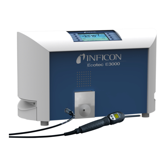
Instrument Views of the Ecotec E3000 Fig. 1-2 Instrument views of Ecotec E3000 Pos. Description Pos. Description Main display Lemo Connector for sniffer line Handle for carrying the Ecotec E3000 Speaker ECO-Check reference leak Installation 1.6.1 Set up Caution The weight of the Ecotec E3000 exceeds 25 kg. It therefore should not be carried by one single person. - Page 24 Fig. 1-3 Removing the transportation lock before starting Caution Before installation remove the transportation lock. Caution In order to ensure adequate ventilation of the Ecotec E3000, a space of at least 20 cm (8 in.) must be kept unobstructed to the sides. The clearance at the rear must be no less than 10 cm (4 in.).
-
Page 25: Mechanical Connections
1.6.2 Mechanical Connections ECO-Check Reference leak (optional) Please insert the ECO-Check reference leak into the opening in the housing of the main unit. Make sure that the Sub-D plug is properly connected with the ECO-Check leak. Notice: When properly inserted, the ECO-Check reference leak will still protrude by approx. - Page 26 Holder for SL3000 sniffer line (optional) An optional holder for the SL3000 sniffer line is available as cat.-no. 525-006. The holder may be installed on the right or left side of the main unit (for right- or left handed operators) as shown in Fig.
- Page 27 Water protection tip (optional) If you intend to perform leak testing on parts that are not completely dry (e.g. due to condensation after performance testing), we strongly recommend to use a water protection tip. To install the water protection tip, screw off the metallic capillary filter at the very end of the sniffer tip and install the water protection tip instead.
-
Page 28: Electrical Connections
For Ecotec E3000RC only The Ecotec E3000RC has no built-in display unit but a connectors plate is mounted instead. Please connect the external display unit with the 5 m connecting table (Cat.- no. 551-102). Fig. 1-8 Ecotec E3000RC with external display unit for: (a) bench top use (left side), (b) rack mounting (right side) 1.6.3 Electrical Connections... -
Page 29: Rs232 Interface
The mains voltage is applied to the Ecotec E3000 via the detachable mains cable which is supplied with the Ecotec E3000. A main power socket is available for this purpose at the rear of the Ecotec E3000. Caution Before connecting the Ecotec E3000 to the mains you must make sure that the mains voltage rating of the Ecotec E3000 coincides with the locally available mains voltage. - Page 30 1-20 General Information...
-
Page 31: How The Instrument Works
How the Instrument Works Description of the Functions The Ecotec E3000 is capable of detecting and quantifying the refrigerant sucked in through the sniffer line by means of a selective mass spectrometer. The Ecotec E3000 is composed of the following principal subassemblies: •... -
Page 32: Description Of The Subassemblies
Description of the Subassemblies 2.2.1 Backing Pump A diaphragm pump in the Ecotec E3000 serves as the backing pump. All data and further information on this pump are given in the Operating Instructions of the pump. The backing pump generates the fore pressure required for operation of the turbo molecular pump and sucking in of the gas through the sniffer line. -
Page 33: Displays And User Interfaces
Displays and User Interfaces 2.3.1 Main unit display This subassembly is used to communicate with the operator. It accepts commands from the 8 keys on both sides of the display and outputs measurement results and messages via the display. Fig. 2-2 Main unit display Pos. -
Page 34: Sniffer Line With Probe Display
The external display unit also offers four buttons: • The START / STOP buttons have no function (the external display unit may also be used with other INFICON leak detectors which need these buttons) • The MENU button will open the software menu. - Page 35 The right probe button is used for different functions depending on the current operating mode the Ecotec E3000 is set to. Fig. 2-5 Probe handle The probe handle also offers some LEDs in the flange of the sniffer tip in order to illuminate the location currently being leak tested.
-
Page 36: Built-In Eco-Check Reference Leak
2.3.3 Built-in ECO-Check reference leak A built-in ECO-Check reference leak is available for the Ecotec E3000. The ECO- Check reference leak can be used for verifying the correct functioning of the Ecotec E3000 including the correct calibration and can also be used for re-calibrating the Ecotec E3000 if necessary. - Page 37 In cases where the main unit is placed in a difficult or inconvenient to access area the built-in ECO-Check reference leak can be removed from the main unit for easier access and connected to the main unit via the Sub-D connector with a commonly available extension cord.
- Page 38 How the Instrument Works...
-
Page 39: Operation Of The Ecotec E3000
Operation of the Ecotec E3000 Start-Up Assemble the Ecotec E3000 (see Section 1.5). Connect the mains cord and the sniffer line, and then switch on the Ecotec E3000. The mains switch is located on the rear. Fig. 3-1 Connection of the mains cord Pos. -
Page 40: Controls On The Main Display Unit
After switching on and completion of the run-up phase the Ecotec E3000 will be ready to make measurements. There is no separate start function. The sniffer lines are designed to maintain an inlet pressure low enough to make measurements. Notice: The Ecotec E3000 will only operate after having connected the sniffer line. - Page 41 Bar graph display The currently detected leak rates for all selected gases will be display in a bar graph for each gas independently in logarithmic scale. On the upper left side of each bar graph the selected gas type is indicated. The currently selected trigger level is indicated by a black line, the currently selected search level is indicated by a dotted line.
- Page 42 Menu Button The button on the bottom left side of the display will open the main menu at any time. The menu mode offers the user many possibilities of entering Ecotec E3000 settings and special functions. Cal Button With the button on the upper right side of the display an external calibration of the Ecotec E3000 can be started at any time.
-
Page 43: Controls On The Probe Display Unit
Controls on the probe display unit On the display of the probe handle similar information as on the main display is shown. Pos. Description Bar graph indicating the leak rate Absolute leak rate Gas currently detected Fig. 3-5 Sniffer display in standard operation mode The currently detected leak rate is indicated as a bar graph. -
Page 44: Performing Measurements
Performing measurements The Ecotec E3000 offers two modes of operation: • The Standard Operation Mode (compatible to the EcotecII mode) • The I•Guide Operating Mode Warning Danger of electric shock. Do not touch voltaged parts with the sniffer tip. Test samples need to be disconnected from electricity before leak testing. - Page 45 Fig. 3-6 Sniffer display when detecting a leak The display limits for the different units of measurement are summarized in the table below. Unit Lower display limit Upper display limit 0.05 1,000 oz/yr 0.002 1,000 100,000 mbar l/s 1x10 9.9x10 Pa m³/s 1x10 9.9x10...
-
Page 46: I•Guide Operating Mode
3.4.2 I•Guide Operating Mode The I•Guide operating mode has been introduced to support the operator in applying proper sniffer leak detection technique. The I•Guide operator guiding mode allows to store pre-programmed parameters for different units under test. The number of locations that need to be tested per specimen, the time each location needs to be tested for as well as the time required to move to the next location may be programmed. -
Page 47: Selecting An I•Guide Program
3.4.2.2 Selecting an I•Guide Program To open the “ • ” menu press the ” ” button on the right side SELECT I GUIDE PROGRAM LIST of the display. Fig. 3-8 Measuring Screen in I•Guide Mode Pos. Description program list In the opening “... - Page 48 Fig. 3-10 I•Guide screens during measurement (one gas selected) Pos. Description Pos. Description Pos. Description Selected program Elapsing measuring ZERO button Gas type stored in the time I•Guide button selected program Summarized global I•Guide message leak rate per unit under test Fig.
- Page 49 the message “please wait” will be displayed in the message line until a next measurement is allowed. Please confirm that the sniffer tip has been positioned properly by pressing the right probe button so that the next measurement can be started. Fig.
-
Page 50: The Info Page
Fig. 3-14 Result of I•Guide program: unit under test failed The sniffer line display will switch to red background color if the global trigger is exceeded (or at least one if two gases are selected for the program used). The gas exceeding the global trigger is displayed in the results list. However, you can switch between the results of the two different gases with the "A"... - Page 51 Fig. 3-16 Info page with active warning When operating in I•Guide Mode, the info page will state information about the currently selected program: the selected program name, the gas used for this program, the number of points to be checked for this program, the selected measuring and wait time as well as the global trigger.
-
Page 52: Calibration And Self-Test
Calibration and Self-Test The Ecotec E3000 can be calibrated internally with the built-in ECO-Check reference leak or externally with an external calibrated leak (Cat. No. 122 20 - 122 35). The built-in ECO-Check reference leak can be used for a self-test of the Ecotec E3000 as well as for calibration of gases that are measured at mass positions between 40 and 105 amu. -
Page 53: Verifying A Calibration (Proof Function)
3.5.1 Verifying a calibration (proof function) Notice: The description of how to perform a verification applies to the use of the ECO-Check reference leak for detecting helium or hydrogen (forming gas) accordingly. Notice: A verification can only be performed while the Ecotec E3000 is in measurement mode (not when the main menu is opened or during start- up). -
Page 54: Internal Calibration
3.5.2 Internal calibration Notice: The description of how to perform an internal calibration applies to the use of the ECO-Check reference leak for detecting helium or hydrogen (forming gas) accordingly. Notice: An internal calibration can only be performed while the Ecotec E3000 is in measurement mode (not when the main menu is opened or during start- up). -
Page 55: External Calibration
3.5.3 External calibration For external calibration it is recommended to use leak rates > 2 g/a (0.07 oz/yr) when calibrating the Ecotec E3000. Notice: If significantly increased backgrounds are prevalent in your production environment, larger leak rates for the calibration leak may be required. Notice: If a calibration is started during the first 20 minutes after power on, a warning will be issued. - Page 56 Fig. 3-21 Setting-up the leak rate of the external leak Please hold the sniffer tip to the outlet of the external calibrated leak. Hold the sniffer tip steady and very close to the opening, however, do not clog the opening with the sniffer tip.
-
Page 57: Shutdown
In the opening info page the name of the gas, the currently selected trigger value and the measurement mode will be displayed. This info is followed by the value for the lower display limit and the status of the internal calibration. In addition, the currently selected mass position, the calibration factor for the chosen gas, the date of the last calibration and type of the last calibration are listed. - Page 58 3-20 Operation of the Ecotec E3000...
-
Page 59: Equipment Settings
Equipment Settings Menu Structure By pressing the button the main menu page opens. The following options will MENU be displayed: Fig. 4-1 Main menu screen In the subsequent sub-menus the following frequently used functions will occur: The “up” and “down” keys allow scrolling through listed menu items. The currently selected menu item is highlighted by inverted colours. - Page 60 2 Start / Sleep 3 Service 5 Gas Trigger 5 Gas 1 Name 8 Edit 6 Gas 2 Mode (Gas) 7 Gas 3 Trigger&Unit 8 Gas 4 Search&Limit Internal cal. Mass Cal. Factor Last cal. Cal. Mode 2 User gas User library no.
-
Page 61: Sleep Mode
Sleep Mode When pressing the button in the main menu the Ecotec E3000 will go into SLEEP sleep mode. The sensor will be shut off and all pumps will be powered down. However, the Sleep mode menu is still accessible. button will then be replaced by a button. -
Page 62: Editing Gas Parameters
4.4.1 Editing gas parameters When pressing one of the “ 1” to “ 4” buttons an info page regarding the corresponding gas will open. Changes to the current settings can be made by scrolling to the line item to be changed by use of the “up”... - Page 63 Fig. 4-4 The gas library Six open positions for user-programmable gases can be found at the bottom of the list. Working with gas equivalents (for helium and hydrogen only) When working with helium or hydrogen as a tracer gas you may also display the detected leak rate in a leak rate, e.g.
- Page 64 If you are working with diluted helium or hydrogen as your tracer and / or your helium / hydrogen testing pressure is different from your gas equivalent fill pressure later on, you may also enter gas EQUIVALENT SETTINGS The gas menu button will only be available after an EQUIVALENT SETTINGS EQUIVALENT...
-
Page 65: Selecting Trigger Values And Units Of Measurement
4.4.3 Selecting trigger values and units of measurement In the “ ” info page the sub-menu page will open by selecting EDIT GAS TRIGGER UNIT the “ ” line item. You can change the trigger level setting by the use of the left TRIGGER “up”... -
Page 66: Selecting The Search Level And The Lower Display Limit
4.4.4 Selecting the search level and the lower display limit Fig. 4-9 Editing the search level and the lower display limit as well as the can be edited by going to the SEARCH LEVEL LOWER DISPLAY LIMIT & line item in the submenu and pressing SEARCH LIMIT... -
Page 67: Selecting An Alternative Mass Position
4.4.6 Selecting an alternative mass position When choosing a gas from the gas library a default mass position for the gas to be detected will be chosen automatically. In cases of cross sensitivity with other substances in your leak testing environment it may be advisable to chose an alternative mass position for detecting the required gas. -
Page 68: Activating The Interfering Gas Suppression (Igs)
4.4.7 Activating the Interfering Gas Suppression (IGS) The IGS Mode offers a mode in which interferences between R600a as the refrigerant and Cyclopentane, Isopentane as well as any mixtures of the two will be suppressed. In this mode, the Ecotec E3000 will automatically differentiate between these three gases and should compensate properly for levels of foaming agents not exceeding 50 g/a with an error of less than 1%. - Page 69 Fig. 4-12 Setting up a user-definable gas Name The user gas name is a free text name. When selecting the name line item and pressing edit a 6 digit name can be entered via the alpha-numerical entry keys. Default value: User 1, User 2, User 3, User 4, User 5 Mass position The mass position determines the peak position at which the user-definable will be detected.
-
Page 70: Settings Sub-Menu
Settings Sub-menu In the settings sub-menu several settings which are important for the leak testing procedure can be edited. 4.5.1 Vacuum & Access Menu In the & sub-menu setting monitoring functions like the VACUUM ACCESS ZERO function, the flow limits setting and the sensitivity check can be edited. Zero When pressing the button the... - Page 71 Flow limits In this submenu the minimum and maximum gas flow through the capillary is entered. If the actual gas flow drops below this limit (e.g. if the capillary becomes partially blocked) or exceeds this limit (e.g. if the sniffer line is damaged so that ambient air is sucked in) an alarm is issued.
-
Page 72: Audio Functions
In the CALibration submenu an internal calibration can be ENABLED DISABLED If the function is set to , only a proof function with the built-in ECO-Check DISABLED reference leak will be possible. Default value: ENABLED Change menu PIN Any changes to the current settings may be password protected. The menu PIN can be changed in the “change menu PIN”... - Page 73 Audio intern The internal loudspeaker of the main unit can be switched on and off. This will not effect the headphones outlet. Default value: enabled. Audio sniffer The alarm of the loudspeaker in the probe handle can be set to react to exceeding or exceeding the .
-
Page 74: Display Settings
4.5.3 Display Settings In the submenu the contrast of the display can be changed, the DISPLAY SETTINGS peak hold function, the gas select mode and the user mode can be edited. Contrast In the submenu the contrast of the main unit display can be adjusted. CONTRAST Values between 0 and 99 can be entered. - Page 75 If the function is enable the maximum leak rate will be displayed for a PEAK HOLD preset time in addition to the currently measured value in the main display. The time setting will have no effect if this function is disabled. Default: disable 5 s.
-
Page 76: Setting-Up / Editing An I•Guide Program
4.5.4 Setting-up / editing an I•Guide Program When selecting the button a submenu page will open showing the SETUP PROGRAM list of 10 pre-programmable I•Guide programs and their current status (enabled / disabled). If a program is enabled it will be offered in the list of programs to select from when operating in the I•Guide mode. - Page 77 To edit the parameters of a program select the program by scrolling to the corresponding menu line and open the selected program by pressing the “E ” button. In the opening sub-menu the name of the program and the gas type(s) EDIT PROGRAM selected for this program are stated.
- Page 78 Gas A / B For editing the gas type go to the “ ” or “ ” line item and press “E ”. Only GAS A GAS B gases that are listed in the “ ” submenu (Gas1 to Gas4) are available for TRIGGER selection.
-
Page 79: Miscellaneous Settings
Please use the up and down buttons for editing this parameter. Default value: 1.0 s Wait time between two leak checks allowed to move the sniffer to the next WAIT TIME potentially leaking location can be varied between 0.1 s and 25.0s in steps of 0.1s . Please use the up and down buttons for editing this parameter. - Page 80 Leak rate filter For all normal operation the I•Filter should be selected. I•Filter is an intelligent filtering algorithm that yields the best results with respect to noise level and stability of leak rate values specifically developed for use in the Ecotec E3000 leak detector. Only in cases where the older Ecotec II model is replaced by an Ecotec E3000 and the Ecotec E3000 is used in a fixed testing system it may be required to stick with the “...
-
Page 81: Interfaces
Interfaces In the I submenu the , the , the NTERFACES CONTROL LOCATION RECORDER OUTPUTS , the , the and the B & PROTOCOL PLC INPUTS PLC OUTPUTS AUD RATE END SIGN can be edited. 4.6.1 Control location can be “ ”, “... - Page 82 The voltage range is 0 - 10 V. Beginning at 1V, each leak rate decade is spread over 2 volts, i.e.: 1…3V: 1 decade 3…5V: 2 decade 5…7V: 3 decade 7…9V: 4 decade Thus a leak rate range of 4 decades will be output by way of an analogue signal. The four decades are set through the value and the unit of measurement for the trigger level.
- Page 83 Trigger Leak rate Output voltage 5.35V 0.1 oz/yr 1.5 oz/yr 5.60V 3 g/a 20 g/a 6.39V 50 g/a 2.806V 5 x 10 mbar l/s 8 x 10 mbar l/s 6.556V 6 x 10 mbar l/s Default setting: logarithmic Recorder output gas Here one gas from the four gases is defined which will be output as the analog signal through channel 1.
-
Page 84: Rs232 Protocol
4.6.3 RS232 Protocol The RS232 protocol can be set to “ ”, “ ”, “ ” or “ ASCII DIAGNOSTICS PRINTER AUTO PRINTER ”. MANUAL is a protocol similar to the SCPI, a standard protocol widely used ASCII PROTOCOL for measuring equipment. For details on this protocol please refer to the Interface Description (kins22e1). -
Page 85: Baud Rate & End Sign
Point no. Date Time Leak rate Unit Point 03 12.2 Point 04 Global 13.04.2007 11:57:03 12.5 4.6.4 Baud rate & end sign can be set to values between 1200 and 19200. Default setting: 9600. BAUD RATE can be set to Carriage Return (CR), Line Feed (LF) or to CR+LF. END SIGN Default setting: CR+LF. -
Page 86: Select Plc Outputs
4.6.6 Select PLC Outputs In the submenu the user can select which pin on the I/O port SELECT PLC OUTPUTs (suitable for PLC output) represents which command. There are four PLC outputs and two relays outputs available. The default setting is as follows: PLC outputs Command Command... -
Page 87: Eco-Check (Only Available In Advanced Mode)
4.6.7 ECO-Check (only available in A Mode) DVANCED In this submenu the ECO-Check reference leak can be disabled completely so that for Ecotec E3000 leak detectors without an ECO-Check onboard the Ecotec E3000 does not check for the electrical connection with the reference leak anymore and no error message is issued. -
Page 88: The Info Menu
The Info Menu lists all internal data that may be useful for any trouble-shooting of the INFO MENU Ecotec E3000. The info menu consists of 8 pages. On each page the upper left button “ ” allows to leave the info menu, the lower left button allows to go back BACK one page whereas the lower right button allows to go to the next page. - Page 89 Menu item Format Description Run-up time Software version xxxxxx Page 3: Transpector data Configuration Box version x.xx Control SW version x.xx Measure SW version x.xx Filament des./act. A / B Desired filament / active filament Power on time Emission on time A Emission on time B TSP temperature °C / °F...
- Page 90 Menu item Format Description Type SL3000 / system Software version Length 3 m / 5 m / 10 m / 15 m Serial no. 9000 XXX XXXX Switch left Switch right Backlight Green / red Bar graph Flow at calibration sccm Page 6: I/O Port data Recorder A...
- Page 91 Menu item Format Description AIN9 +15V MC50 AIN10 +24V MC50 AIN11 +24V I TSP AIN12 +24V II TMP Page 8: Analog data AIN0 AIN0 offset Foreline pressure mbar AIN1 Flow sccm AIN2 Page 9: RS232 Info Ecotec E3000 sniffer ASCII string Command sent from main unit to sniffer...
-
Page 92: History & Maintenance
History & Maintenance In the & menu page historical data that has been collected HISTORY MAINTENANCE during the operation of the Ecotec E3000 can be viewed. This includes error lists, a listing of the calibration history and a service list. The available functions depend on the current user mode, in „S “... - Page 93 View error list In the all errors (and warnings) that have occurred during the operation ERROR LIST of the Ecotec E3000 are summarized. In the list the when the error occurred is stated followed by error or DATE TIME warning number ( being errors and being warnings) with a short description of the error or warning.
- Page 94 • The date and time of calibration • The number of operation hours at time of calibration • The calibration factor • The peak position (as deviation from mass position) • The flow through the sniffer line at the time of calibration •...
- Page 95 Maintenance history In the list all maintenance tasks performed are listed. MAINTENANCE HISTORY The date and the time the maintenance tasks were performed, the number of operation hours the unit had worked at the time when the maintenance task was performed and the type of maintenance that was conducted are listed.
- Page 96 Replace ECO-Check user mode only) ADVANCED When replacing the gas reservoir of the ECO-Check reference leak, the new serial number of the replacement gas reservoir as well as a code containing the calibration data of the new reservoir needs to be entered in this submenu. For details on how to replace the gas reservoir of the ECO-Check reference leak please refer to Section 8.8.
-
Page 97: Monitoring Sensitivity
Monitoring Sensitivity It is highly recommended to always keep the function enabled. SENSITIVITY CHECK This function should only be disabled when operating in argon-free environment as the argon signal is used for monitoring. For details on this function see Section 4.5.1 (“Sensitivity Check”) If sensitivity changes,... - Page 98 4-40 Equipment Settings...
-
Page 99: Ecotec E3000 Messages
In the following table all possible error messages and the recommendations stated in the display in case of this error are listed. If no recommendation is given, please call your nearest INFICON service representative (see Section 1.2.1). Ecotec E3000 Messages... - Page 100 Fuse F5 on the motherboard has blown Replace fuse F5 on motherboard* 5V of the internal Leak too low ECO-Check electronics defective Replace ECO-Check reference leak or call nearest INFICON service representative! -15V of the MC50 is too low Motherboard defective Call nearest INFICON service...
- Page 101 Error no. Plain text message Possible reason Recommendation Remove sniffer from CAL port Sniffer inserted in calibration port during Remove sniffer from calibration port start-up of ECO-Check! sniffer needs to be removed during internal calibration process Light barrier of ECO-Check dirty Blow out with fresh air and / or clean with cotton swab! Real time clock reset! Please enter...
- Page 102 INFICON service representative. No communication with Transpector! Software cannot establish Check cable connection between communication with Transpector Transpector and CPU-board!* Call nearest INFICON service representative! Transpector temperature > 70°C or < Air filter dirty Replace main air filter (see Section 0°C! 8.3.)
- Page 103 No emission with first filament! Start emission failed with first filament ! Switch to Unkown TC-Error Failure of the turbo electronic drive Call nearest INFICON service representative! No communication with turbo controller Software cannot establish Call nearest INFICON service communication with controller of TMP...
- Page 104 (especially during external calibration) value! (see Section 3.5.3) Test leak not sniffed properly / not long Repeat calibration, sniff test leak enough properly and for sufficient time Baseline Transpector not found Severe Transpector problem Call nearest INFICON service representative! Ecotec E3000 Messages...
- Page 105 Error in the motor stages or control Call nearest INFICON service control representative! F007: Mains power failure Mains power failure operations voltage Call nearest INFICON service has failed representative! Operations voltage has failed * only to be performed by INFICON-authorized service personnel Ecotec E3000 Messages...
- Page 106 Ecotec E3000 Messages...
-
Page 107: Detecting Specific Gases
Detecting Specific Gases R134a / Cyclopentane When detecting R134a in presence of cyclopentane (foaming agent) R134a should be detected on the alternative mass position 83 to avoid false alarms due to cross sensitivity with the cyclopentane. Please refer to section 4.4.6 for how to select an alternative mass position. -
Page 108: Hydrogen / Forming Gas
A test leak with a leak rate of > 14 g/a is required for external calibration of the Ecotec E3000. An external test leak “TL4-6 for methane” is available from INFICON as part no. 12249 for this purpose. Detecting Specific Gases... -
Page 109: Equipment Connections
Equipment Connections The Ecotec E3000 is equipped with three electrical control connectors. The electrical connections (head phone, I/O port and RS232) are located on the rear of the Ecotec E3000 directly next to the socket for the mains cable. I/O Port (Control Inputs and Outputs) Warning For all contacts of the I/O Port a maximum voltage of 60 V DC or 25 V AC must not be exceeded or reached to ground or ground equipment conductors. -
Page 110: Ground Connectors
7.1.1 Ground connectors Pin 2, 3, 18, 19 and 21 are ground connectors of the control voltages. 7.1.2 24V Output Pin 6 is a +24 V common output for supplying the PLC inputs and outputs, internally protected with fuse F4. 7.1.3 PLC Inputs These inputs can be used to control the Ecotec E3000 via a programmable logic... -
Page 111: Plc Outputs
Gas select, gas a, gas b Through the control inputs (pin 9, 13 and 25 of the 25 way Sub-D connector) it is possible to select a gas loaded in the active gas memory (one gas out of four). The Ecotec E3000 will then operate in the single gas mode. -
Page 112: Relay Outputs
Open collector output Active = low Pin assignment (default) Default Command Ready not used Leak Error All PLC outputs can be defined by the user from a list of commands. The commands can be selected in the SETTINGS / INTERFACES / SELECT PLC OUTPUTS submenu. -
Page 113: Recorder Outputs
Pin assignment (default) Type of contact Relay Output (default) Currentless closed (NC) Leak Common Currentless open(NO) Currentless closed (NC) Ready Common Currentless open (NO) All PLC outputs can be defined by the user from a list of commands. The commands can be selected in the SETTINGS / INTERFACES / SELECT PLC OUTPUTS submenu. -
Page 114: How To Perform A Calibration
7.1.5 How to perform a calibration An external calibration may be performed via the PLC inputs and outputs. For this purpose, one of the inputs needs to be configured to "CAL", another needs to be set to "CAL AIR" (for how to select PLC inputs see section 4.6.4). The external calibration is always performed for the enabled gas with the highest gas no. -
Page 115: Rs232 Interface
RS232 interface The RS232 interface can be used for external control of the Ecotec E3000 but also for simple export of data describing testing results. For how to set-up the RS232 interface please refer to Section 4.6. For a detailed description of the RS232 interface and its commands please refer to the “Ecotec E3000 Interface Description”... -
Page 116: Maintenance
Key for Maintenance Schedule: • Repair level Customer • Repair level Customer with technical training from INFICON • Repair level INFICON service engineer 1 To be replaced every 3 years. 2 Date printed on package is latest installation date. 3 Maximum shelf life: 1 year. -
Page 117: Adjusting The Igs Function
Adjusting the IGS function (only in user mode) ADVANCED If you are using the IGS function for suppressing false alarms from Cyclopentane or Isopentane as foaming agent in combination with R600a as the refrigerant, this function may need an adjustment (calibration) for the two interfering gases Cyclopentane and Isopentane if you observe an increasing number of false alarms. -
Page 118: Exchanging The Air Filter
Exchanging the air filter Caution The air filter should be checked for contamination at least every 6 months and should be definitely exchanged after 2 years. Warning Before exchanging the filter, the Ecotec E3000 must be disconnected from power. To exchange the air filter, place the Ecotec E3000 on its front-side or position it on the edge of a sturdy bench. - Page 119 Fig. 8-2 Dismounting of the air filter Depending on the contamination the air filter should be cleaned or replaced as necessary. Slide in new (cleaned) air filter until fully in contact with dead stop. Fig. 8-3 Inserting the air filter Close air filter fastener.
-
Page 120: Replacing The Operation Fluid Reservoir
Under normal operating conditions the operation fluid reservoir needs to be exchanged at least once a year. Under extreme stress or dirty environment, please contact your INFICON Service representative for special recommendations. Notice: The operation fluid reservoir has a limited shelf life. Please order only when needed. - Page 121 Fig. 8-4 Screw out the end cover Lift out the operation fluid reservoir Using tweezers, pull out Porex rods ( 8 pieces) Fig. 8-5 Removing the operation fluid reservoir Fig. 8-5 Pos. Description Operation Fluid Reservoir Porex rod Using tweezers, insert Porex rods ( 8 pieces) Maintenance...
- Page 122 Insert new operation fluid reservoir into the pump up to the O-Ring (see Fig. 8-6). Fig. 8-6 O-Ring of operation fluid reservoir Caution Do not completely push in the operation fluid reservoir. The operation fluid reservoir is correctly positioned by the cover after screwing it in. Re-assemble bottom lid.
-
Page 123: Exchanging The Mains Fuses
Exchanging the mains fuses Warning Before exchanging the fuses you must disconnect the mains cord. Only fuses of the specified type and rating are to be used as replacements. Use a screw driver to fold out the lid of the mains socket from the right (the mains switch is not affected by this). -
Page 124: Replacing Filters In The Sniffer Line
Replacing filters in the sniffer line If the sniffer probe is clogged, a warning “Flow through capillary too low” (warning 35) will be issued. Clogging of the sniffer probe may be due to: • Clogging of capillary filter: see Section 8.6.1 •... - Page 125 Fig. 8-9 Pushing out filter pads Fig. 8-10 old and new filter pads Push in new filter pads. Notice: The metal grid is not included with the spare filter pads. Please clean the metal grid carefully and use it again. Switch on the Ecotec E3000.
-
Page 126: Replacing The Felt Discs (With Water Protection Tip)
8.6.2 Replacing the felt discs (with water protection tip) Switch off Ecotec E3000! Screw off water protection tip! Push out filter pads and metal grid from the back side. Re-install metal grid at the bottom of water protection tip. Push in two new filter pads (all the way to the bottom of the water protection tip). Switch on Ecotec E3000 Notice: If the flow has changed by more than 30%, a re-calibration of the Ecotec... -
Page 127: Switching The Capillary Filter
Remove the sinter filter with the o-ring. Fig. 8-12 Sinter filter Visually check the filter for contamination. Install a new sinter filter with o-ring at the bottom of the filter tip. Reinstall the sniffer tip. Switch on the Ecotec E3000. Hold finger against the capillary filter: You should be able to feel the resulting vacuum. -
Page 128: Switching From Metal To Plastic Capillary Filter
8.7.1 Switching from metal to plastic capillary filter When you switch from the metal capillary filter to the plastic capillary filter you need to remove the taper gasket. The plastic capillary filter will not fit with the taper gasket installed. Remove the two Philips screws in the flange of the sniffer tip and remove sniffer tip. -
Page 129: Switching From Plastic To Metal Capillary Filter
The capillary may be removed in that way for the following sniffer tips: cat. no. length 122 09 FT600 600 mm flexible 122 13 ST312 120 mm rigid 122 14 FT312 120 mm flexible 122 15 ST385 385 mm rigid 122 16 FT385 385 mm... - Page 130 Fig. 8-16 Removing the ECO-Check reference leak from the main unit and dismounted Screw off the gas reservoir counter clockwise, use hex nut key if necessary. Caution Inside of the holder is a glass tube and one O-ring which protects the photocell against dirt (Fig.
- Page 131 Fig. 8-18 Installing the gas reservoir Notice: Screw in the new reservoir with hex nut key only! Re-install the ECO-Check in the Ecotec E3000. Notice: The ECO-Check does not fit in the Ecotec E3000 completely. There is a little gap between the front panel of the Ecotec E3000 and the ECO-Check. Fig.
- Page 132 Notice: The Ecotec E3000 must be set to user mode for confirming ADVANCED maintenance tasks. (Go to SETTINGS DISPLAY USERMODE Notice: The ECO-Check reference leak must be installed in the Ecotec E3000 when pressing OK. Fig. 8-20 Entry screen for replacing the ECO-Check Notice: Entering the new leak relevant codes is important as otherwise an accurate calibration with the internal test leak and traceability of the calibration...
- Page 133 8-18 Maintenance...
-
Page 134: Annex
Annex The gas library The operating software of the Ecotec E3000 contains a list of about 100 gases which are relevant to the refrigerating industry. These gases are stored in a ROM (read only memory) and from the list contained in this memory gases and trigger levels may be selected through the corresponding sub-menus. - Page 135 Gas designation Other Designations Meas. mass Molecule mass Normalisation factor (max. 5 digits) (xxx.x amu) (xx.x amu) (Base value x.xEx) 69.0 88.0 7.0E7 50.0 88.0 7.0E8 CHCI 67.0 102.9 7.0E7 69.0 102.9 3.5E8 CHCIF 51.0 86.5 7.6E7 67.0 86.5 7.6E7 69.0 70.0 2.4E8...
- Page 136 Gas designation Other Designations Meas. mass Molecule mass Normalisation factor (max. 5 digits) (xxx.x amu) (xx.x amu) (Base value x.xEx) R125 51.0 120.0 7.0E7 101.0 120.0 7.0E7 R134a 69.0 102.0 1.1E8 83.0 102.0 1.1E8 51.0 102.0 1.1E8 R141b 81.0 117.0 7.0E7 67.0 117.0...
- Page 137 Gas designation Other Designations Meas. mass Molecule mass Normalisation factor (max. 5 digits) (xxx.x amu) (xx.x amu) (Base value x.xEx) R290 Propane C 41.0 44.1 7.0E7 39.0 44.1 7.0E7 42.0 44.1 3.5E8 R356 Blend of 77.0 166.1 7.0E7 x CF 69.0 166.1 7.0E7...
- Page 138 Gas designation Other Designations Meas. mass Molecule mass Normalisation factor (max. 5 digits) (xxx.x amu) (xx.x amu) (Base value x.xEx) R404A Blend of 69.0 97.6 9.3E7 44% R125 52% R143a 51.0 97.6 9.3E7 4% R134a 101.0 97.6 9.3E7 R405A Blend of 51.0 111.9 7.0E7...
- Page 139 Gas designation Other Designations Meas. mass Molecule mass Normalisation factor (max. 5 digits) (xxx.x amu) (xx.x amu) (Base value x.xEx) R409B Blend of 51.0 96.7 7.0E7 65% R22 25% R124 67.0 96.7 7.0E7 10% R142b R410A Blend of 51.0 72.6 1.2E8 50% R32 50% R125...
- Page 140 Gas designation Other Designations Meas. mass Molecule mass Normalisation factor (max. 5 digits) (xxx.x amu) (xx.x amu) (Base value x.xEx) R416A Blend of 69.0 111.9 7.0E7 59% R134a 39.5% R124 67.0 111.9 7.0E7 1.5% R600 R500 Blend of 85.0 99.3 7.0E7 74% R12 26% R152a...
- Page 141 Gas designation Other Designations Meas. mass Molecule mass Normalisation factor (max. 5 digits) (xxx.x amu) (xx.x amu) (Base value x.xEx) R600 41.0 58.1 7.0E7 Butane 42.0 58.1 7.0E7 R600a 41.0 58.1 2.0E8 Iso-Butane 42.0 58.1 2.0E8 58.0 58.1 2.0E8 R601 41.0 72.2 7.0E7...
- Page 142 Gas designation Other Designations Meas. mass Molecule mass Normalisation factor (max. 5 digits) (xxx.x amu) (xx.x amu) (Base value x.xEx) Xenon 132.0 131.3 7.0E7 127.0 146.1 9.1E7 HT135 Galden HT135 1.2E7 7.0E7 7.0E7 7.0E7 7.0E7 ZT130 Galden ZT130 7.0E7 1.2E7 1.2E7 1.2E7 1.2E7...
-
Page 143: Declaration Of Conformity
Declaration of Conformity 9-10 Annex... - Page 144 Appendix 4-13 flow limit 1-18 fuse accessories 4-17 advanced mode air filter gas flow 4-14 4-15 alarm – gas library 4-22 alarm delay 4-19 4-20 global trigger – ambient temperature audio volume – 1-12 autozero 4-34 history 1-12 4-12 background 1-18 1-19 I/O Port...
- Page 145 4-23 1-13 recorder output transportation lock 3-11 3-12 3-15 4-26 right probe button – – trigger 4-17 4-26 1-11 4-30 turbo molecular pump – 1-18 1-19 4-23 RS232 interface – turbo molecular pump (TMP) 4-26 RS232 protocol 4-17 User mode 3-14 self-test 4-13...
- Page 146 INFICON GmbH, Bonner Strasse 498, D-50968 Cologne, Germany Phone: +49 (0)221 347-40 Fax: +49 (0)221 347-41429 E-mail: leakdetection@inficon.com UNITED STATES TAIWAN JAPAN KOREA SINGAPORE GERMANY FRANCE UNITED KINGDOM HONG KONG Vi s i t o ur w eb s i t e f o r c on ta c t i nf o rma t i on an d o t he r s al es of f i c e s w or l dwi de . w w w. i n fi c o n . com...
Need help?
Do you have a question about the Ecotec E3000 530-001 and is the answer not in the manual?
Questions and answers