Inficon Ecotec E3000 Original Operating Instructions
Leak detector
Hide thumbs
Also See for Ecotec E3000:
- Technical handbook (146 pages) ,
- Translation of the original operating instructions (104 pages)

Subscribe to Our Youtube Channel
Related Manuals for Inficon Ecotec E3000


Summary of Contents for Inficon Ecotec E3000
- Page 1 Translation of the original operating instructions Ecotec E3000 Leak detector Order no.: 530-001, 530-002 from software version: 530-103, 530-104 3.14...
- Page 2 Reprint, translation and duplication need to be approved in writing by INFICON GmbH.
-
Page 3: Table Of Contents
Table of Contents About this manual ................................ 5 Target group ................................... 5 Other applicable documents ............................ 5 Presentation of information ............................5 1.3.1 Warnings ..................................5 Safety ....................................7 Intended use ................................... 7 Owner requirements ..............................7 Operator requirements ............................... 8 Dangers .................................... - Page 4 Replacing the filter inserts of the capillary filter and the water conservation tip ....... 72 8.2.5 Replacing the sinter filter of the sniffer handle ....................73 Taking out of service ..............................75 Disposal of the Ecotec E3000 ..........................75 Returning the Ecotec E3000 ........................... 75 Appendix ..................................77 10.1 Accessories ..................................
-
Page 5: About This Manual
About this manual This document applies to the software version stated on the cover page. Documents for other software versions are available from our sales department. Target group These operating instructions are intended for the owner of the leak detection unit E3000 and for technically qualified personnel with experience in leak detection technology and integration of leak detection devices in leak detection systems. - Page 6 1 About this manual...
-
Page 7: Safety
Safety Intended use The device is a leak detector for sniffer leak detection. With the device you locate and quantify leaks on test objects. The device sniffs for light gases, refrigerants and natural gases. The test objects must contain the gas under overpressure. The outsides of the test objects are checked for escaping gas with a sniffer line (sniffing method). -
Page 8: Operator Requirements
► If you have questions regarding operation or maintenance that you cannot find answers for in these instructions, please contact the INFICON customer service. Dangers The unit was built according to the state of the art and the recognized safety regulations. -
Page 9: Shipment, Transport, Storage
Shipment, transport, storage Table 1: Scope of delivery Scope of delivery Article Quantity Ecotec E3000 (main unit) Power supply cable, 3 m length Fuses Replacement air filter 8 mm Allen wrench 19 mm box wrench Operating instructions Interface description Check the scope of delivery of the product for completeness after receipt. - Page 10 3 Shipment, transport, storage...
-
Page 11: Description
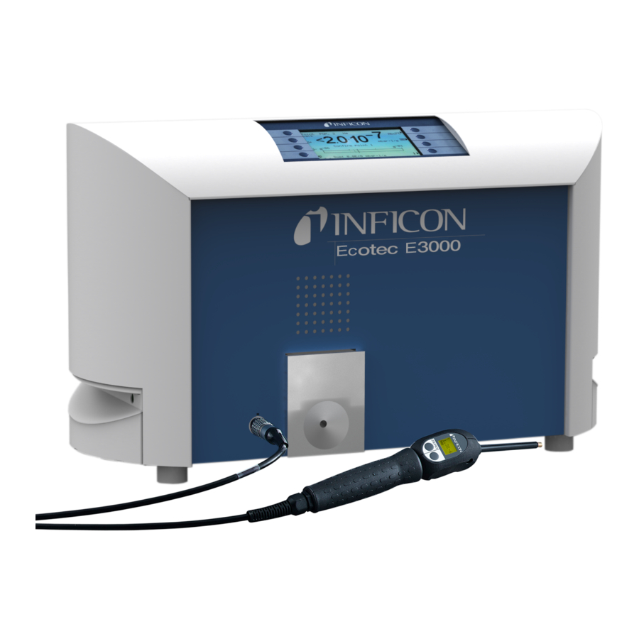
Function and setup of the device The Ecotec E3000 is comprised of main unit and sniffer line. The Ecotec E3000 can verify and quantify gases sucked in by the sniffer line with the help of a selective mass spectrometer. Working in the Ecotec E3000: ... - Page 12 In order to better hear signals in a loud environment, you can connect head phones. b Inputs/outputs (I/O port) The I/O port enables communication with a PLC. Some functions of the Ecotec E3000 can be controlled from the outside and measurement results and device states of the Ecotec E3000 can be transmitted to the outside.
-
Page 13: Sniffer Line
g Rating plate The rating plate contains the supply voltage specification and other information with which the device can be clearly identified. Fig. 3: Rating plate Supply voltage Serial number Production date Sniffer line You need a sniffer line to operate the device. Sniffer lines are available in four lengths: 3 m, 5 m, 10 m and 15 m. -
Page 14: Technical Data
If the measuring value limit is exceeded, the display switches from green to red. You can additionally set one speaker in the handle to output a signal and the LEDs in the handle to flash or shine with maximum brightness, see “6.3 Settings before measurements”, page Technical data Table 2: Technical data... - Page 15 Table 2: Technical data (cont.) Response time 3 m sniffer line 0.7 sec. 5 m sniffer line 0.9 sec. 10 m sniffer line 1.4 sec. 15 m sniffer line 3.0 sec. Table 3: Factory settings Alarm profile Trigger alarm Alarm delay Deactivated Number of measuring points (I•Guide) Functions...
- Page 16 Table 3: Factory settings (cont.) Control location Local and RS-232 Search threshold 90 % Trigger value, sum (I•Guide) 10 g/a Trigger and unit 4 g/a Idle time (I•Guide) 3 seconds Maintenance, sniffer probe filter 100 hours Zero time 5 seconds Zero key sniffer line Activated ZERO key main unit...
-
Page 17: Installation
Operate the Ecotec E3000 only in a dry environment. ► Operate the Ecotec E3000 away from sources of liquid and moisture. ► Danger due to dropping heavy loads The device is heavy and can damage persons and items through tilting or dropping. -
Page 18: Connecting The Sniffer Line
The transport restraint blocks the mechanical system in the device. ► Remove the transport restraint before the start-up. The transport restraint is on the bottom of the Ecotec E3000 and consists of a yellow star screw. Fig. 5: Unscrew the yellow transport restraint before the start-up... -
Page 19: Replacing The Plastic Capillary Filter With The Metal Capillary Filter
Metal capillary filter Plastic capillary filter 5.2.1.1 Replacing the plastic capillary filter with the metal capillary filter 1 Turn off the Ecotec E3000. 2 Unscrew the plastic capillary filter. 3 Insert the plugwasher, see fig. 6 on page 4 Screw in the metal capillary filter on the sniffer probe end. -
Page 20: Water Conservation Sniffer Probe Mounting And Remove
7 Screw the plastic capillary filter on the sniffer probe. 8 Calibrate the Ecotec E3000, see “6.4.2 Calibration”, page 5.2.1.3 Water conservation sniffer probe mounting and remove With the help of the water conservation sniffer probe, you can check test objects with low surface moisture, e.g. -
Page 21: Attaching The Sniffer Lines Holder
Connecting the ECO-Check calibrated leak A built-in calibrated leak (ECO-Check) and different external calibrated leaks are available as accessories available for the Ecotec E3000, see “10.1 Accessories”, page Please refer to the ECO-Check installation manual on how to connect the ECO-Check. -
Page 22: Connecting To The Power Supply System
Connecting to the power supply system The supply voltage of the Ecotec E3000 is specified on the labeling of the mains plug (rating plate). The Ecotec E3000 cannot be switched for other supply voltages. Danger due to incorrect supply voltage Incorrect supply voltage can destroy the device and injure persons. -
Page 23: Operation
There is no separate start function. But you have to still calibrate the device and make different settings for your intended measurement. If the ECO-Check calibrated leak is not in the Ecotec E3000, an acoustic warning signal and the warning 71 are output during the first start-up. -
Page 24: Recurring Function Symbols
6.2.1.1 Recurring function symbols The keys are always assigned with the following functions and labeled with the shown symbols. Setting the volume for speakers and head phones. Set volume: The set volume is displayed on the bottom edge of the display. Value range: 0 (off) to 10 (max.) –... -
Page 25: Elements Of The Measurement View
6.2.2 Elements of the measurement view The measured leak rates are shown numerically and with logarithmically divided bar graph displays. The other elements of the measurement view are shown in the following figure. Fig. 13: Elements of the measurement view Leak rate unit Bell: search threshold exceeded;... -
Page 26: Operating Elements And Display On The Sniffer Handle
If the ZERO function is activated, the word “ZERO” follows in the status line. If the first cathode (filament A) of the mass spectrometer has been consumed and the Ecotec E3000 switches automatically to the second cathode (filament B), the display will show “Fil. B” in the status line. -
Page 27: Special Features Of The Ecotec E3000Rc
The current measured background value is set as zero point with the ZERO key, “Zero”, page The START / STOP keys do not have any function (the external display unit can also be used with other leak detectors made by INFICON that require these keys). 6 Operation... -
Page 28: Settings Before Measurements
Only in cases in which the older Ecotec II model was replaced with an Ecotec E3000 and the Ecotec E3000 is used in a fixed test device can it be necessary to select the older filter settings “Auto” or “Fixed”. -
Page 29: Audio Settings
► Wake up If the Ecotec E3000 is in idle state (sleep), a time can be set for it to start automatically. This way you can set the Ecotec up to run through its warm-up phase already before the shift starts. -
Page 30: Display Settings
Table 4: Features of the alarm profiles Alarm profile pinpoint Alarm profile setpoint Alarm profile trigger/alarm Search value exceeded – Acoustic signal low frequency Acoustic signal low frequency Trigger value exceeded – Acoustic signal high Two-tone signal frequency Acoustic tracing of the <... -
Page 31: Gas Display Handle
The factory setting with black font on light background can be inverted. This causes the display to emit less light overall. Peak hold You can set if and how long the highest measured value is to be displayed additionally below the current leak rate. Setting range: 0 to 20 seconds. - Page 32 Monitoring check The sensitivity check in the device ensures that the sensitivity of the Ecotec E3000 is always sufficient. The entire gas flow from sniffer probe to sensor is monitored and the software simultaneously checks whether the Ecotec E3000 can determine the correct signal strength with it.
-
Page 33: Interfaces
Some settings can be changed on the device. Please use the protection via access PIN if all functions on the device are to be inaccessible, “Changing the menu PIN”, page Local and RS-232: The Ecotec E3000 can be controlled via interface and entries on the device. Linear Recorder outputs >... -
Page 34: Settings For The Measurements
If you do not use an ECO-Check calibrated leak, you should choose “Deactivate” here. Otherwise, warning 71 “No communication with ECO-Check” will be issued at every start of the Ecotec E3000. If you use an ECO-Check calibrated leak, you can set up a warning for the intended time of use here: 14/30/60/90 days. - Page 35 Fig. 20: Changing the settings for gas 1 With the keys up and down you select a setting. Pressing the key “change” on the bottom right opens the associated settings menu. The gas to search for is displayed. You can open the gas library with “change” and choose from approx.
- Page 36 The following table shows the adjustable units and the associated limits for the trigger value. Table 5: Trigger value according to unit Unit Lower trigger value limit Upper trigger value limit 1000 oz/yr 0.004 999999 2 10 9.9 10 mbar l/s 2 ...
-
Page 37: Calibration
The ECO-Check calibrated leak includes R134a. It can be used for the calibration of gases with a mass position from 40 to 105 amu because the Ecotec E3000 converts the calibration result for the measurement of these gases. -
Page 38: Internal Calibration With Eco-Check
(see “Internal calibration”, page 36) is displayed. The Ecotec E3000 notices if you insert the sniffer tip in the opening of the calibrated leak and starts calibration automatically. Messages subsequently guide you through the calibration process. A warning is displayed if the device has not be switched on for 20 minutes yet. Simply confirm the warning and then continue with calibration if you know that the device has reached operating temperature because it was switched off only briefly before calibration. -
Page 39: External Calibration With External Calibrated Leak
6.4.2.2 External calibration with external calibrated leak For external calibration of the Ecotec E3000, we recommend calibrated leaks with leak rates > 2 g/a. If background concentrations in the testing environment are clearly increased, a calibrated leak with a higher leak rate is required. -
Page 40: Gas Equivalent To Helium And Hydrogen, Settings For Diluted Gas
You can also take a different pressure and/or different concentration between original gas and gas equivalent into consideration. An internal conversion of the measurement result thus allows the Ecotec E3000 to approximate the result of a leak pre-check close to the result of a main leak examination. -
Page 41: Suppressing Interfering Gases (Sophisticated Interfering Gas Suppression - Igs)
The bottom right shows the correction factor of helium/Hydrogen based on the gas equivalent. If a set of parameters that exceeds the limits of the Ecotec E3000 is entered, the correction factor is displayed with inverted colors. In this case, adjust the parameter until the correction factor display returns to normal. -
Page 42: Setting A User-Defined Gas
For the additional IGS alignment, you need a cyclopentane test leak and an isopentane test leak, available as “Calibration set for IGS mode”. The Ecotec E3000 recognizes errors you make in the gas sequence during the alignment and notifies you with a flashing gas display. -
Page 43: Measuring
The standard factor is used to convert the current supplied by the sensor into a leak rate signal. If you are setting a user-defined gas, the Ecotec E3000 should subsequently be calibrated with an external test leak, if possible. If calibration is successful, you will not modify the standard factor. - Page 44 Danger of eye damage LEDs generate a bundled light that can damage eyes. ► Do not look into the LEDs from a short distance or for a longer period of time. Electric shock hazard Sucked in liquids can trigger short circuits and cause damage to property or personal injury.
-
Page 45: Calling Up Information On The Measurement
Because of the high measuring sensitivity of the device and because interfering gases can falsify the measurement result, you should repeat the measurement if a leak has been reported. Remember to suppress the background again beforehand (press the left key on the sniffer handle). -
Page 46: Setting The I•Guide Program
one or two gases trigger values for the gases number of measuring points measurement time per measuring point idle time between measurements (transition to next measuring point) maximum permissible overall leak rate for the part to be tested The right key on the sniffer handle must be pressed in order to confirm the measurement at an individual measuring point. -
Page 47: Starting The I•Guide Program
Fig. 34: List of I•Guide programs 5 Select the setting you wan to change with the arrow keys and press “Change”. 6 Adjust the setting as described in the following are and confirm with “OK”. Name Name of the program. A name comprises six characters. After you have entered the last character, you can confirm with “OK”. - Page 48 1 If due, calibrate the device externally. During the work with I•Guide, the device can be calibrated internally only. 2 Activate I•Guide in the I•Guide menu, see above. A message shows the gas that is being searched for. It is the gas from the first activated I•Guide program. Confirm with “OK”. 3 Switch to the main menu.
- Page 49 Fig. 37: Search for gas R134a with I•Guide program 1: The trigger value and the overall leak rate were exceeded at measuring points 1 and 3 The next measurement cycle starts if you confirm with “OK” or press the right key on the sniffer handle.
-
Page 50: Idle State (Sleep)
If you press the SLEEP key in the main menu of the device, the device goes into idle state. The mass spectrometer is switched off and the pumps are stopped. “Sleep” is replaced with “START” In the main menu and the Ecotec E3000 is run up again with “START” or the wake-up function. - Page 51 Table 7: Device information Menu item Format Description Page 1: General data Backing pressure mbar Pressure on the mass spectrometer inlet Flow sccm Flow through the sniffer line Total pressure mbar Pressure in the mass spectrometer Time since power on Operating hours Serial number 9000 XXX XXXX...
- Page 52 Table 7: Device information (cont.) Menu item Format Description Test leak temperature °C / °F Status of light barrier Page 5: Sniffer line information Type SL3000 / system Software version Length 3 m / 5 m / 10 m / 15 m Serial no.
-
Page 53: Special Features Of Individual Gases
“6.4.4 Suppressing interfering gases (Sophisticated interfering gas suppression - IGS)”, page Special features with If you are sniffing for helium, the Ecotec E3000 needs longer for an analysis than with helium refrigerants. Therefore stick to the following times during which you will not move the sniffer tip. -
Page 54: Switching Off The Device
Therefore use the external calibrated leak “TL4-6 for methane” for calibration. Switching off the device You can switch off the Ecotec E3000 at any time with the mains plug (position “0”). It takes a few minutes for the turbo molecular pump to come to a standstill. The Ecotec E3000 must not be moved during that time. -
Page 55: Warnings And Error Messages
Error messages Errors are events that the Ecotec E3000 cannot remedy itself and that force an interruption of operation. The error message consists of a number and a description. After you have removed the cause of the error, start operation again with the restart key. - Page 56 E22 TMP frequency is too low! The sniffer line is incorrectly connected. Check the connection. The turbo molecular pump is defective. Contact the INFICON customer service. E23 Turbo pump frequency too high! The turbo molecular pump is defective. Contact the INFICON customer service.
- Page 57 Confirm the error message and restart the device. If the (The emission on both cathodes cannot of time, this error can occur during the first problem still exists: Contact the INFICON customer be switched on.) 10 minutes after start-up. service.
- Page 58 Confirm the error message and restart the device. If the (The emission failed during operation.) of time, this error can occur during the first 10 problem still exists: Contact the INFICON customer minutes after start-up. service. – The input pressure is too high.
- Page 59 The ECO-Check calibrated leak cannot be addressed Check the connection to the ECO-Check calibrated leak. by the main unit. If the problem still exists: Contact the INFICON customer service. No ECO-Check calibrated leak connected. Connect an ECO-Check calibrated leak. If you do not want...
- Page 60 Contact the INFICON customer service. molecular pump E92 Run-up time error (E006) The turbo molecular pump does not run up correctly. Contact the INFICON customer service. E93 Connection electronic drive unit - pump The connection between the control and the turbo Contact the INFICON customer service.
- Page 61 Contact the INFICON customer service. (E026) E98 Error in the motor stage or the control There is an error in the motor stages or the control. Contact the INFICON customer service. (E037) E99 Error on the power supply (F007) The supply voltage has failed.
- Page 62 7 Warnings and error messages...
-
Page 63: Maintenance
The error history includes the errors and warnings that occurred during the operation of the Ecotec E3000. Date and time are shown followed by an identification for the error or the warning (E… with errors and W… with warnings), with a brief description of the error or the warning. - Page 64 Fig. 42: Calibration list To have the complete calibration information displayed, select the appropriate line and press the key with the magnifying glass. The calibration information includes: Calibration mode (internal or external); for internal: gas in calibrated leak Gas –...
- Page 65 Maintenance history The maintenance history shows all maintenance work that was confirmed within the scope of the work. Shown are date and time of completed works, the number of operating hours of the device at the time of the maintenance work and the type of work performed. To have the complete entry displayed, select the appropriate line and press the key with the magnifying glass.
-
Page 66: Maintenance Work
If an ECO-Check calibrated leak is connected or the gas store of the ECO-Check us replaced, you have to enter the serial number as well as the identification with the calibration data. The installation of the ECO-Check in the Ecotec E3000 as well as the gas store replacement are described in the ECO-Check manual. - Page 67 Felt for capillary filter 200 001 116 the water conservation tip. Clean or replace the main air filter in the floor of Air filter Ecotec E3000 (104 x 154 mm; 200 001 552 the housing. 5 pcs.) Check the internal filter and replace, if necessary...
-
Page 68: Replacing The Air Filter Of The Main Unit
8.2.1 Replacing the air filter of the main unit The air filter is inside a duct that is accessible from the bottom of the device. The duct is closed with a cover plate. The cover plate is held in place with a 3-mm hexagon socket screw. -
Page 69: Replacing The Operating Fluid Reservoir
8 soaked sticks (Porex rods). Plastic container and Porex rods are below the turbo molecular pump and accessible from the bottom of the Ecotec E3000. The bore for the operating fluid reservoir is closed with an aluminum plug and a plastic screw. - Page 70 Fig. 48: Fastener of the operating fluid reservoir 4 Lever out the aluminum plug with one or two narrow screw drivers. 5 Hook something into the center bore of the plastic container and pull out the plastic container. Fig. 49: Opened operating fluid reservoir 6 Pull the eight Porex rods out of the front side of the bore with tweezers.
-
Page 71: Replacing Mains Fuses
8 Place the plastic container in the bore with the soaked liner first and close it with the aluminum plug. 9 Tighten the plastic screw again. Ensure that the o-ring is placed correctly in the groove of the plastic screw and that the bore is lined up properly. 10 Confirm the work, see “Confirm maintenance”, page 8.2.3... -
Page 72: Replacing The Filter Inserts Of The Capillary Filter And The Water Conservation Tip
The filter inserts are pushed inside and are in front of a small metal grill that is also pushed inside. To replace filter inserts, proceed as follows: 1 Turn off the Ecotec E3000. 2 Unscrew the capillary filter or the water conservation tip. Make sure that the plugwasher does not fall out. -
Page 73: Replacing The Sinter Filter Of The Sniffer Handle
Replacing the sinter filter of the sniffer handle The sinter filter is in the sniffer handle. To replace filter inserts, proceed as follows: 1 Turn off the Ecotec E3000. 2 Unscrew the two cross-head screws that hold the sniffer probe in place. - Page 74 8 Maintenance...
-
Page 75: Taking Out Of Service
Taking out of service Disposal of the Ecotec E3000 The device can be disposed of by the owner or sent to INFICON. The device is made of materials that can be reused. You should use this option to avoid waste and protect the environment. - Page 76 This form can be downloaded Copies: from our website. Original for addressee - 1 copy for accompanying documents - 1 copy for file of sender INFICON GmbH Bonner Str. 498,50968 Cologne, Germany zisa01e1-b (1106) Tel: +49 221 56788-112 Fax: +49 221 56788-9112 www.inficon.com leakdetection.service@inficon.com...
-
Page 77: Appendix
Appendix 10.1 Accessories Table 12: Accessories and order no. Accessory part Order no. Sniffer line SL3000-3, 3 m length 525-001 SL3000-5, 5 m length 525-002 SL3000-10, 10 m length 525-003 SL3000-15, 15 m length 525-004 Sniffer line for system integration (robotic application) 525-015 Sniffer probes ST 312, 120 mm length, rigid... -
Page 78: Gas Library
10.2 Gas library The software of the Ecotec E3000 includes a list with approx. 100 gases that can be relevant for the refrigeration industry. These gases are saved to ROM (read only memory) and can be selected from the list in the appropriate menus for gases and trigger values. - Page 79 Table 13: Gases and their mass position (cont.) Formula Other Measuring position Molecular mass Fragmentation Normalization factor Viscosity designation (xxx amu) (xxx.x amu) factor (x.xExx) R13B1 149.0 1.00 3.5E+07 0.852 0.12 0.12 0.10 0.10 80.0 1.00 7.0E+07 0.857 0.70 CHFCl 102.9 1.00 7.0E+07...
- Page 80 Table 13: Gases and their mass position (cont.) Formula Other Measuring position Molecular mass Fragmentation Normalization factor Viscosity designation (xxx amu) (xxx.x amu) factor (x.xExx) R143a 84.0 1.00 7.0E+07 0.561 0.35 R152a 66.1 1.00 8.7E+07 0.515 0.47 R170 Ethane 30.1 1.00 7.0E+07 0.591...
- Page 81 Table 13: Gases and their mass position (cont.) Formula Other Measuring position Molecular mass Fragmentation Normalization factor Viscosity designation (xxx amu) (xxx.x amu) factor (x.xExx) R403A 75 % R22 92.0 1.00 7.0E+07 0.642 20 % R218 0.35 5 % R290 R403B 56 % R22 103.3...
- Page 82 Table 13: Gases and their mass position (cont.) Formula Other Measuring position Molecular mass Fragmentation Normalization factor Viscosity designation (xxx amu) (xxx.x amu) factor (x.xExx) R410B 45 % R32 75.6 1.00 7.0E+07 0.673 55 % R125 0.35 R411A 1.5 % R1270 82.4 1.00 7.0E+07...
- Page 83 Table 13: Gases and their mass position (cont.) Formula Other Measuring position Molecular mass Fragmentation Normalization factor Viscosity designation (xxx amu) (xxx.x amu) factor (x.xExx) R503 40 % R23 87.3 1.00 7.0E+07 0.709 60 % R13 0.35 R504 48 % R32 79.3 1.00 7.0E+07...
- Page 84 Table 13: Gases and their mass position (cont.) Formula Other Measuring position Molecular mass Fragmentation Normalization factor Viscosity designation (xxx amu) (xxx.x amu) factor (x.xExx) R1234z(e) C 114.0 1.00 3.4E+08 0.600 0.82 0.48 R1243z(f) C 96.0 1.00 2.9E+08 0.600 0.52 0.48 0.41 0.85...
-
Page 85: Menu Tree
10.3 Menu tree 2 Start / sleep 3 Service Service PIN 5 Measuring parameter 5 Gas 1 8 Edit 6 Gas 2 Status 7 Gas 3 Trigger&Unit 8 Gas 4 Search & Limit Internal calibration Mass and position Cal. factor Last calibration Cal. -
Page 86: Ce-Declaration Of Conformity
10.4 CE-Declaration of Conformity 10 Appendix... -
Page 87: Rohs-Declaration Of Conformity
10.5 RoHS-Declaration of Conformity Declaration of RoHS Conformity* Multi-Gas Sniffer Leak Detector Ecotec E3000 Toxic or Hazardous Substances or Elements Lead Mercury Cadmium Hexavalent Polybrominated Polybrominated (Pb) (Hg) (Cd) Chromium biphenyls biphenyl ethers Part Name (Cr(VI)) (PBB) (PBDE) (PBB) Housing... - Page 88 10 Appendix...
-
Page 89: Index
Index Access control 31 Gas display handle 31 Accessories 77 Gas equivalent 40 Air filter Gas library 78 Main unit 68 – Sniffer line 72 – Alarm delay 29, 45 I•Guide 45 Alarm profile 29 program setting 46 – Starting the program 47 –... - Page 90 Time & Date 28 Transport 9 Scope of delivery 9 Transport restraint 18 Search threshold 36 Turbo molecular pump 11 Select filament 66 Sensitivity check 32 – Settings User-defined gas 42 Device 28 – Measurements 34 – Sinter filter sniffer line 73 Vacuum 31 Sleep 50 Volume 30...
- Page 91 Index...
- Page 92 INFICON GmbH, Bonner Strasse 498, D-50968 Cologne, Germany leakdetection@inficon.com UNITED STATES TAIWAN JAPAN KOREA SINGAPORE GERMANY FRANCE UNITED KINGDOM HONG KONG Vis it our web si te fo r co nta c t in fo r ma t io n a nd o t her s a l e s of f ices wo r ld wi de. w w w.i nf ico n.co m...
Need help?
Do you have a question about the Ecotec E3000 and is the answer not in the manual?
Questions and answers