Advertisement
Quick Links
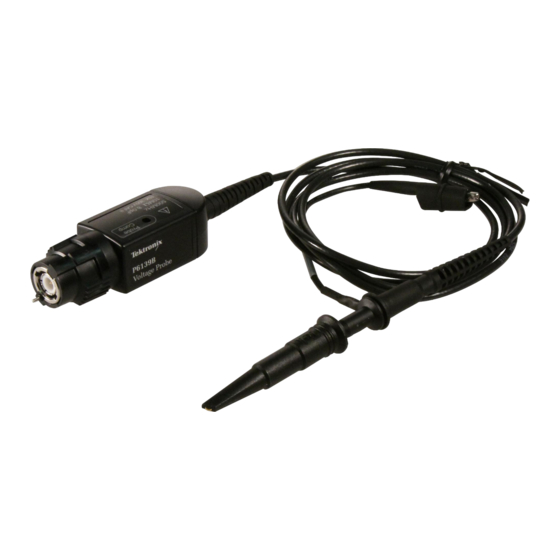
P6139B & P5050B
500 MHz 10X Passive Probes
Instructions
Revision A
* P071271000*
x
071-2710-00
500 MHz 10X Probes
The P6139B & P5050B probes are high impedance,
passive probes that are designed for use with Tektronix
ground-referenced oscilloscopes, including the
DPO/MSO/TDS 3000/4000/5000/7000 series oscilloscopes.
Both probes have a bandwidth of >500 MHz and 10X
attenuation. The P6139B probe has a compensation range
of 8 to 18 pF, while the P5050B probe has a compensation
range of 15 to 22 pF.
Connecting the Probe to the Oscilloscope
Connect the probe to the oscilloscope as shown below.
Compensating the Probe
Due to variations in oscilloscope input characteristics,
the low-frequency compensation of the probe may need
adjustment after moving the probe from one oscilloscope
channel to another.
If a 1 kHz calibrated square wave displayed at 1 ms/division
shows significant differences between the leading and
trailing edges, perform the following steps to optimize
low-frequency compensation:
1.
Connect the probe to the oscilloscope channel that you
plan to use for your measurements.
2.
Connect the probe to the probe compensation output
terminals on the oscilloscope front panel.
WARNING.
To avoid electric shock, only connect to the
Probe Comp signal on the oscilloscope when making
this adjustment.
To avoid electric shock, only use the insulated adjustment
tool when making compensation adjustments.
Test Equipment Depot - 800.517.8431 - 99 Washington Street Melrose, MA 02176 - TestEquipmentDepot.com
3.
Push AUTOSET or otherwise adjust your oscilloscope
to display a stable waveform.
4.
Adjust the trimmer in the probe until you see a perfectly
flat-top square wave on the display. (See illustration.)
Standard Accessories
The accessories included with the probe are shown below.
WARNING.
To avoid electric shock when using the probe
or accessories, keep fingers behind the finger guard of
probe body and accessories.
To reduce risk of shock, verify that the ground lead and
ground spring are fully mated before connecting the
probe to the circuit under test.
Item
Description
Universal IC Cap
Use this cap to prevent shorting
the probe tip between IC pins.
Press the cap on the probe tip
until it snaps on, and then spin
the cap to expose the probe tip
toward the IC lead.
Reorder Tektronix part number
013-0366-xx
Hook tip
Press the hook tip on the probe
tip and then clamp the hook on
the circuit.
Rating: 300 V CAT II
Reorder Tektronix part number
013-0362-xx
Color bands
Use these bands to identify
the oscilloscope channel at the
probe head.
Reorder Tektronix part number
016-0633-xx (5 pairs)
Item
Description
Ground lead, with alligator
clip
Attach the lead to the probe
head ground and then to your
circuit ground.
Reorder Tektronix part number
196-3521-xx
Ground spring
This spring minimizes
aberrations on high frequency
signals caused by ground
path inductance, giving you
measurements with good signal
fidelity.
Attach the spring to the ground
band on the probe tip. Bend the
spring in or out, up to ~0.75 in.
Reorder Tektronix part number
016-2028-xx
Adjustment tool
Use only this insulated tool for
compensation adjustments.
Reorder Tektronix part number
003-1433-xx
Optional Accessories
The accessories shown below are available for the probes
and are rated ≤30 V unless indicated otherwise.
Accessory
Part number
MicroCKT Test Tip
206-0569-xx
013-0363-xx
Micro Hook TipRating: 300 V CAT II
BNC to Tip Adapter, Unterminated
013-0367-xx
Circuit Board Test Point/PCB Adapter
016-2016-xx
131-4210-xx
Chassis-Mount Probe Test Jack
6" Clip-on Ground Lead
196-3198-xx
12" Alligator Ground Lead
196-3512-xx
016-2034-xx
Ground Spring, Short
Advertisement

Related Manuals for Tektronix P6139B


Summary of Contents for Tektronix P6139B
- Page 1 Push AUTOSET or otherwise adjust your oscilloscope Item Description to display a stable waveform. The P6139B & P5050B probes are high impedance, Ground lead, with alligator passive probes that are designed for use with Tektronix clip Adjust the trimmer in the probe until you see a perfectly ground-referenced oscilloscopes, including the flat-top square wave on the display.
- Page 2 Characteristic Description Avoid electric overload. To avoid injury or fire hazard, do not apply potential to any input, including the reference Order Tektronix part number 206-0635-xx (P6139B) or Pollution Do not operate in environments where cond– inputs, that varies from ground by more than the maximum 206-0636-xx (P5050B).
Need help?
Do you have a question about the P6139B and is the answer not in the manual?
Questions and answers