Table of Contents
Advertisement
Quick Links
Advertisement
Table of Contents

Related Manuals for Tektronix P6022


Summary of Contents for Tektronix P6022
- Page 1 P6022 Current Probe Instruction Manual *P070094805* 070-0948-05...
- Page 3 P6022 Current Probe Instruction Manual Warning The servicing instructions are for use by qualified personnel only. To avoid personal injury, do not perform any servicing unless you are qualified to do so. Refer to all safety summaries prior to performing service.
- Page 4 Copyright © Tektronix. All rights reserved. Licensed software products are owned by Tektronix or its subsidiaries or suppliers, and are protected by national copyright laws and international treaty provisions. Tektronix products are covered by U.S. and foreign patents, issued and pending. Information in this publication supersedes that in all previously published material.
- Page 5 Warranty Tektronix warrants that the product will be free from defects in materials and workmanship for a period of one (1) year from the date of original purchase from an authorized Tektronix distributor. If the product proves defective during this warranty period, Tektronix, at its option, either will repair the defective product without charge for parts and labor, or will provide a replacement in exchange for the defective product.
-
Page 7: Table Of Contents
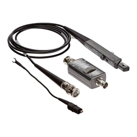
Operating Considerations ..................Service Information ....................Warranted Characteristics..................Typical Characteristics ..................Circuit Description ................... Probe Performance ................... Performance Verification..................P6022 Test Record.................... Adjustment Procedure..................Maintenance ....................Replaceable Electrical Parts ..................Parts Ordering Information .................. Using the Replaceable Parts List................Replaceable Mechanical Parts.................. - Page 8 Table of Contents List of Figures Figure 1: P6022 probe, termination, and ground lead ............Figure 2: Connecting the probe and termination to the oscilloscope ......... Figure 3: Insertion impedance of the probe ..............Figure 4: Probe and termination input current vs. frequency derating ........
- Page 9 Table 3: Maximum ratings ..................Table 4: Electrical characteristics................Table 5: Mechanical characteristics ................Table 6: Equipment list ................... Table 7: P6022 low frequency bandwidth measurements............. Table 8: High frequency bandwidth measurements ............Table 9: P6022 test record ..................Table 10: Replaceable electrical parts................
-
Page 10: General Safety Summary
Avoid Exposed Circuitry. Do not touch exposed connections and components when power is present. Do Not Operate in Wet/Damp Conditions. Do Not Operate in an Explosive Atmosphere. Keep Product Surfaces Clean and Dry. Terms in this Manual These terms may appear in this manual: P6022 Instruction Manual... - Page 11 DANGER indicates an injury hazard immediately accessible as you read the marking. WARNING indicates an injury hazard not immediately accessible as you read the marking. CAUTION indicates a hazard to property including the product. The following symbol(s) may appear on the product: P6022 Instruction Manual...
-
Page 12: Service Safety Summary
Use Care When Servicing With Power On. Dangerous voltages or currents may exist in this product. Disconnect power, remove battery (if applicable), and disconnect test leads before removing protective panels, soldering, or replacing components. To avoid electric shock, do not touch exposed connections. P6022 Instruction Manual... -
Page 13: Compliance Information
Pollution Degree 3. Conductive pollution, or dry, nonconductive pollution that becomes conductive due to condensation. These are sheltered locations where neither temperature nor humidity is controlled. The area is protected from direct sunshine, rain, or direct wind. P6022 Instruction Manual... - Page 14 Compliance Information Pollution Degree 4. Pollution that generates persistent conductivity through conductive dust, rain, or snow. Typical outdoor locations. Pollution Degree Pollution Degree 2 (as defined in IEC 61010-1). Note: Rated for indoor use only. viii P6022 Instruction Manual...
-
Page 15: Environmental Considerations
Union requirements according to Directives 2002/96/EC and 2006/66/EC on waste electrical and electronic equipment (WEEE) and batteries. For information about recycling options, check the Support/Service section of the Tektronix Web site (www.tektronix.com). Restriction of Hazardous This product has been classified as Monitoring and Control equipment, and is outside the scope of the 2002/95/EC RoHS Directive. - Page 16 Compliance Information P6022 Instruction Manual...
-
Page 17: Operator Information
The P6022 probe is compatible with general-purpose ground-referenced oscilloscopes having a 1 MΩ input impedance. The P6022 probe comes with a passive termination that matches oscilloscope and probe impedance, optimizes the probe performance, and provides two sensitivity settings. -
Page 18: Installation
To ensure the best performance from your probe/oscilloscope measurement system, check that the probe and oscilloscope are appropriately matched. The oscilloscope inputs should use BNC connectors, and have an impedance of 1 MΩ. Figure 2: Connecting the probe and termination to the oscilloscope P6022 Instruction Manual... - Page 19 Operator Information Attaching the Probe 1. Connect the termination box female BNC end to the P6022 probe output cable. and Termination to an 2. Connect the termination box male BNC end to a ground-referenced Oscilloscope oscilloscope. WARNING. To avoid electric shock and possible injury, do not apply any voltage above earth ground potential to the probe common lead (do not float the common).
- Page 20 Accessories This instruction manual — Read these instructions to familiarize yourself with the features, specifications, and operation of the P6022 current probe. 6-inch ground lead — Use the 6-inch ground lead to ground the shield around the probe transformer at the probe end of the cable. This allows you to move the ground connection closer to the circuit you are measuring, thereby improving high frequency response.
-
Page 21: Operating Considerations
P6022 probe. Features and Controls Sensitivity Control — The P6022 termination has a control that allows you to select probe sensitivity. The switch has two positions: 1 mA/mV and 10 mA/mV. When the control is in the 1 mA/mV position, the oscilloscope displays 1 mV for every 1 mA of current in the circuit under test. - Page 22 The conductor now becomes the primary of the transformer. (When measuring current, always check that the probe slide switch is moved completely forward into the locked position.) P6022 Instruction Manual...
-
Page 23: Figure 3: Insertion Impedance Of The Probe
This additional impedance affects signals; this is particularly important if you are measuring fast rise times. The equivalent circuit with additional impedance introduced by the P6022 is shown below. Figure 3: Insertion impedance of the probe Minimizing Loading Effect To minimize the loading effect of the probe, clamp it at the low or ground end of a component lead when possible. - Page 24 Operator Information Probe Shielding The P6022 probe is shielded to minimize the effect of external magnetic fields. However, strong fields can interfere with the current signal being measured. If you suspect that an external field is interfering with your measurement, remove the probe from the conductor, but keep it in the same location as when you made the suspect measurement.
-
Page 25: Service Information
Service Information Service Information Warranted Characteristics This section lists the various warranted characteristics that describe the P6022 Current Probe. Included are warranted electrical and environmental characteristics. Warranted characteristics are described in terms of quantifiable performance limits that are warranted. The warranted electrical characteristics listed apply under the following... -
Page 26: Figure 4: Probe And Termination Input Current Vs. Frequency Derating
The lacquer coating can be easily nicked or damaged, which compromises the insulating capabilities of the lacquer coating. Figure 4: Probe and termination input current vs. frequency derating P6022 Instruction Manual... -
Page 27: Typical Characteristics
Service Information Typical Characteristics This section lists the various typical characteristics that describe the P6022 Current Probe. Included are typical electrical and mechanical characteristics. Typical characteristics are described in terms of typical or average performance. Typical characteristics are not warranted. -
Page 28: Circuit Description
As indicated on the probe body, the turns ratio of the P6022 is 50:1. This refers to the number of windings in the secondary of the probe transformer. -
Page 29: Probe Performance
first aid and resuscitation is present. This section provides procedures to check the performance of the P6022 probe, or to calibrate it. These procedures require the equipment listed. (See Table 6 on page 14.) Specifications given are the minimum necessary for accuracy. -
Page 30: Table 6: Equipment List
Measurement functions Amplitude averaging Calibration generator Fast rise time Rise time ≤1 ns Wavetek 9100 with option 100:250 or Tektronix PG 506A into 50 Ω Sinewave voltage into 50 Ω (100 mA), Wavetek 9100 with option 100:250, or Tektronix SG... -
Page 31: Performance Verification
Service Information Performance Verification Check Midband Accuracy Refer to the illustration below when making equipment connections. Figure 5: Midband accuracy test setup P6022 Instruction Manual... - Page 32 5. Measure and record the DMM output as M1. 6. Disconnect the coax cable from the BNC-to-dual banana adapter. 7. Connect the P6022 termination and probe to the BNC-to-dual banana adapter. 8. Connect the probe to the calibration fixture. 9. Record the DMM output as M2.
- Page 33 2. Connect the BNC-to-dual banana adapter to the input of the DMM. 3. Connect the P6022 termination and probe to the BNC-to-dual banana adapter that is connected to the DMM. 4. Set the P6022 termination sensitivity to 1 mA/mV.
-
Page 34: Figure 6: High Frequency Bandwidth Test Setup
Service Information Table 7: P6022 low frequency bandwidth measurements Probe Probe sensitivity sensitivity M2/M1 M4/M3 1 mA/mV 50 kHz 8.5 kHz 10 mA/mV 50 kHz 935 Hz Check High Frequency Refer to the figure below when making equipment connections. Bandwidth... - Page 35 2. Connect the calibration fixture to the Leveled Sinewave Output of the calibration generator. 3. Connect the P6022 termination and probe to CH1 of the oscilloscope. 4. Set the oscilloscope Vertical Deflection to 20 mV/div. 5. Set the oscilloscope Horizontal Scale to 10 μs/div.
-
Page 36: Table 8: High Frequency Bandwidth Measurements
15. Record the results in the test record and compare the results against the high frequency specification. (See Table 1 on page 9.) 16. Set the P6022 termination sensitivity to 10 mA/mV. 17. Set the oscilloscope Vertical Deflection to 2 mV/div. -
Page 37: P6022 Test Record
Service Information P6022 Test Record Photocopy this form and use it to record the performance test results. Table 9: P6022 test record Instrument Serial Number: Certificate Number: Temperature: Relative Humidity %: Date of Calibration: Technician: Performance test Range, mA/mV Minimum... -
Page 38: Adjustment Procedure
1. Insert a small screwdriver between the cover and the termination near the part number, and gently pry up only the top cover from the P6022 termination by twisting the screwdriver. Leave the bottom cover on, as it must remain in place whenever the termination is in use. -
Page 39: Figure 7: Connecting The Probe To The Calibration Fixture
2. Set the fast rise output to maximum (1 V 3. Connect the P6022 cable BNC connector to the termination. 4. Connect the P6022 termination to the oscilloscope Ch 1 input. 5. Set the P6022 termination sensitivity to 1 mA/mV. -
Page 40: Maintenance
When cleaning the probe, look for any excessive wear of the slide parts that might cause the probe to operate improperly. Dirty or worn mating surfaces between the transformer and the lid can degrade low-frequency response. Clean these surfaces if necessary. P6022 Instruction Manual... -
Page 41: Figure 9: Disassembling The Probe
find any small pieces that may drop. (See Figure 9.) CAUTION. To avoid degrading the performance of the probe, do not touch the polished mating surfaces of the transformer after cleaning. Figure 9: Disassembling the probe P6022 Instruction Manual... - Page 42 10. To reassemble the probe, reverse the procedure above. When replacing the slide switch, spring retainer, and transformer top as a unit, push the slide switch contacts gently inside the sides of the bottom housing. P6022 Instruction Manual...
- Page 43 5. Replace the circuit board by reversing the above procedure. 6. Align the switch with the slider in the front cover and replace the front cover. P6022 Instruction Manual...
-
Page 44: Replaceable Electrical Parts
Replaceable Electrical Parts Replaceable Electrical Parts Parts Ordering Information Replacement parts are available from or through your local Tektronix, Inc. service center or representative. Changes to Tektronix instruments are sometimes made to accommodate improved components as they become available and to give you the benefit of the latest circuit improvements. - Page 45 Chassis-mounted parts have no assembly number prefix and are located at the end of the electrical parts list. Tektronix Part Number Indicates part number to be used when ordering replacement part from Tektronix. (column 2 of the parts list) Serial Number (columns 3 Column three (3) indicates the serial number at which the part was first used.
-
Page 46: Table 10: Replaceable Electrical Parts
RES,FXD,CMPSN:200 OHM,5%,0.125W A2R29 321-0751-06 RES,FXD,FILM:50 OHM,0.25%,0.125W,TC=T9 A2R31 321-0210-00 RES,FXD,FILM:1.50K OHM,1%,0.125W,TC=T0 A2R33 321-0078-00 RES,FXD,FILM:63.4 OHM,1%,125W,TC=T0 A2R34 321-0002-00 RES,FXD,FILM:10.2 OHM,1%,0.125W,TC=T0 A2R35 321-0003-00 RES,FXD,FILM:10.5 OHM,1%,0.125W A2R36 317-0270-00 RES,FXD,CMPSN:27 OHM,5%,0.125W A2R37 317-0300-00 RES,FXD,CMPSN:30 OHM,5%,0.125W A2R39 317-0240-00 RES,FXD,CMPSN:24 OHM,5%,0.125W A2SW30 260-0723-00 SWITCH,SLIDE:DPDT,0.5A,125VAC P6022 Instruction Manual... -
Page 47: Figure 10: P6022 Probe Component Location
Replaceable Electrical Parts Figure 10: P6022 probe component location Figure 11: P6022 termination component Location P6022 Instruction Manual... -
Page 48: Replaceable Mechanical Parts
This section contains a list of the mechanical parts that are replaceable for the P6022. Use this list to identify and order replacement parts. Parts Ordering Information Replacement parts are available from or through your local Tektronix, Inc. service center or representative. Changes to Tektronix instruments are sometimes made to accommodate improved components as they become available and to give you the benefit of the latest... -
Page 49: Table 11: Replaceable Mechanical Parts
Table 11: Replaceable mechanical parts Fig. & index Tektronix Serial number Name & description part no. effective dscont ——– 12 - P6022,PROBE,CURRENT:120 MHZ,100A,5FT W/TERM 204-0360-01 BODY,PROBE:UPPER 214-0581-00 BALL,DETENT:0.062 DIA STEEL 351-0174-00 SLIDE,TEST PROD:ACETAL 214-0735-00 SPRING,HLCPS:0.12 OD X 1.5 L,OPEN ENDS,MUW... -
Page 50: Figure 12: P6022 Exploded View
Replaceable Mechanical Parts Figure 12: P6022 exploded view P6022 Instruction Manual... -
Page 51: Index
7 probe, 7 parts, 2 impedance-matching network, 12 repair, 27 impedance_matching network, 12 shielding, 8, 12 input voltage, maximum, 10 pulse current, maximum, 10 insertion impedance, 7, 11 instruction manual, 4 interference, minimizing, 7, 8, 12 P6022 Instruction Manual... - Page 52 27 sensitivity, 15, 21 replacing connectors, 27 checking, 15, 21 test equipment, 14 specification, 9 winding, 7, 12 oscilloscope settings, 22 sensitivity control, 5, 9, 12 tilt, 11 sensitivity setting, 5, 9, 12 service safety warnings, 13 P6022 Instruction Manual...
Need help?
Do you have a question about the P6022 and is the answer not in the manual?
Questions and answers