Table of Contents
Advertisement
Quick Links
A l l t e s t I n s t r u me n t s , I n c .
5 0 0 C e n t r a l A v e .
F a r mi n g d a l e , N J 0 7 7 2 7
P : ( 7 3 2 ) 9 1 9 - 3 3 3 9
F : ( 7 3 2 ) 9 1 9 - 3 3 3 2
a l l t e s t . n e t
s s a l e s @ a l l t e s t . n e t
T h e t e s t & me a s u r e me n t
e q u i p me n t y o u n e e d a t
t h e p r i c e y o u w a n t .
A l l t e s t c a r r i e s t h e w o r l d ' s l a r g e s t s e l e c t i o n o f
u s e d / r e f u r b i s h e d b e n c h t o p t e s t & me a s u r e me n t
e q u i p me n t a t 5 0 % t h e p r i c e o f n e w .
O O u r e q u i p me n t i s g u a r a n t e e d w o r k i n g , w a r r a n t i e d , a n d
a v a i l a b l e w i t h c e r t i f i e d c a l i b r a t i o n f r o m o u r i n - h o u s e s t a f f
o f t e c h n i c i a n s a n d e n g i n e e r s .
• 1 0 + f u l l t i me t e c h n i c i a n s w i t h o v e r 1 5 0 y e a r s o f
s p e c i a l i z a t i o n
• 9 0 d a y w a r r a n t y & 5 d a y r i g h t o f r e t u r n o n a l l
e q u i p me n t
• • 1 - 3 y e a r w a r r a n t i e s f o r n e w a n d
p r e mi u m- r e f u r b i s h e d e q u i p me n t
• E v e r y u n i t t e s t e d t o O E M s p e c i f i c a t i o n s
• S a t i s f a c t i o n g u a r a n t e e d
Y o u h a v e p l a n s , w e w i l l h e l p y o u a c h i e v e t h e m.
A n y p r o j e c t . A n y b u d g e t .
t
G e t a q u o t e t o d a y !
C C a l l ( 7 3 2 ) 9 1 9 - 3 3 3 9 o r e ma i l s a l e s @a l l t e s t . n e t .
Advertisement
Table of Contents

Subscribe to Our Youtube Channel
Related Manuals for Tektronix P6131


Summary of Contents for Tektronix P6131
- Page 1 T h e t e s t & me a s u r e me n t e q u i p me n t y o u n e e d a t t h e p r i c e y o u w a n t . A l l t e s t I n s t r u me n t s , I n c .
- Page 2 Instruction Manual P6131 10X Passive Probe for 2400 Series Oscilloscopes 070-5514-03 Warning The servicing instructions are for use by qualified personnel only. To avoid personal injury, do not perform any servicing unless you are qualified to do so. Refer to all safety summaries prior to performing service.
- Page 3 Copyright Tektronix, Inc. All rights reserved. Tektronix products are covered by U.S. and foreign patents, issued and pending. Information in this publication supercedes that in all previously published material. Specifications and price change privileges reserved. Tektronix, Inc., P.O. Box 500, Beaverton, OR 97077-1000...
- Page 4 Tektronix, shipping charges prepaid, and with a copy of customer proof of purchase. Tektronix shall pay for the return of the product to Customer if the shipment is to a location within the country in which the Tektronix service center is located.
-
Page 5: Contacting Tektronix
6:00 a.m. – 5:00 p.m. Pacific time Or contact us by e-mail: tm_app_supp@tek.com For product support outside of North America, contact your local Tektronix distributor or sales office. Service Tektronix offers extended warranty and calibration programs as options on many support products. -
Page 6: General Safety Summary
Keep Product Surfaces Clean and Dry. Symbols and Terms Terms in this Manual. The following terms may appear in this manual: WARNING. Warning statements identify conditions or practices that could result in injury or loss of life. P6131 Instruction Manual... -
Page 7: Service Safety Summary
Safety Summary and the General Safety Summary before performing any service procedures. Do Not Service Alone. Do not perform internal service or adjustments to this product unless another person capable of rendering first aid and resuscitation is present. P6131 Instruction Manual... -
Page 8: Operating Basics
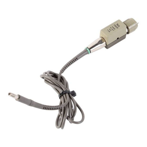
Operating Basics The P6131 probe is a subminiature, 10X, passive probe designed specifically for use with Tektronix 2400 Series oscilloscopes. It is fully compatible with the Tektronix family of subminiature probe accessories. The P6131 is available with 1.3 and 2 meter cable. -
Page 9: Grounding The Probe
WARNING. To avoid electric shock when using the probe, keep your fingers behind the finger guard on the probe body. See Figure 1 below. Hand contact area Finger guard Figure 1: Probe finger guard and hand contact area P6131 Instruction Manual... -
Page 10: Specifications
Specifications The characteristics listed in Table 1 apply to P6131 probes installed on Tektronix 2445 and 2465 oscilloscopes or 7A42 plug-ins, unless otherwise noted. Specifications apply when the instruments warm up for a period of at least 20 minutes in an environment that does not exceed the limits described in Table 2 on page 5. - Page 11 (Duty Factor)] Peak Example: Maximum Input Voltage =[(650 V Pk) (.20)] = 290 V RMS Figure 2: Maximum input voltage calculation example 100K and X 0.01 1000 Frequency (MHz) Figure 3: Typical P6131 X and R versus frequency P6131 Instruction Manual...
- Page 12 Specifications Voltage (RMS) Frequency (MHz) Figure 4: Typical P6131 voltage derating versus frequency Table 2: Environmental characteristics Characteristic Description Temperature range Operating –15 C to 65 C (+5 F to 149 F) Nonoperating –62 C to 85 C (–80 F to 185 F)
- Page 13 Pollution Degree 2 Do not operate in environments where conductive pollutants may be present. Safety UL3111-1, First Edition & IEC61010-2-031, First Edition CSA C22.2 No. 1010.1-92 & CAN/CSA C22.2 No. 1010.2.031-94 EN61010-1/A2 EN61010-2-031 Pollution Degree 2 P6131 Instruction Manual...
-
Page 14: Service Information
Performance Verification Procedure Use the following procedure to verify that P6131 probe performs as warranted. For a list of the warranted specifications, see page 3. Table 5 lists the test equipment needed to perform the performance verification and adjustment procedures. - Page 15 300 MHz output. If you use the probe with a Tektronix 2445 oscilloscope, the bandwidth specification is lower; see Table 1 on page 3. The maximum sensitivity of the 7A42 plug-in is 20 mV/division. When using the 7A42 to check P6131 probes, double the amplitude settings in the procedures to follow.
- Page 16 4. Adjust the calibration generator variable amplitude control to produce a precise 5-division display on the oscilloscope. 5. Note the oscilloscope deflection error directly from the calibration generator display for the calculation in step 9 below (Example: +1%). P6131 Instruction Manual...
-
Page 17: Adjustment Procedure
Service Information 6. Remove the coax cable from the test setup. Connect the P6131 probe output to the same vertical input on the oscilloscope. 7. Connect the probe tip through the probe-tip-to-BNC adapter to the standard amplitude output of the calibration generator. (You must remove the light gray probe-body shell before inserting the probe tip into the probe-tip-to- BNC adapter.) - Page 18 5. Using the low-reactance alignment tool, adjust C2010 to optimize the square wave front corner edge. See Figure 6 for the adjustment location; see Figure 7 for waveform optimization criteria. 6. Disconnect the test setup. Metal-shell version C2010 Plastic-shell version Figure 6: Low-frequency compensation adjustment locations P6131 Instruction Manual...
- Page 19 Plastic shell version: Pry off the darker portion of the plastic shell by inserting your thumbnails into the seam between the two cover pieces; then remove the lighter portion from the inner metal shield. P6131 Instruction Manual...
- Page 20 The overshoot should not exceed the typical aberrations described in step 10 above. 14. Reinstall the compensation box cover by performing the procedure described in step 7 above in reverse order. 15. Disconnect the test setup. P6131 Instruction Manual...
- Page 21 Service Information R2010 C1010 R2021 R2020 Metal-shell version R2010 R2020 R2021 C1010 C2010 Plastic-shell version Figure 8: High-frequency compensation adjustment locations 20 ns R2021 5 ns R2021 3 ns R2021 C1010 Figure 9: High-frequency compensation, optimizing the waveform P6131 Instruction Manual...
-
Page 22: Maintenance
Service Information Maintenance Use the following procedures to clean and maintain the P6131 probe. Cleaning To remove accumulated dirt from the probe exterior, use a soft cloth dampened with a nonresidue cleaner, preferably isopropyl alcohol. In particular, avoid solvents such as benzene, toluene, xylene, or acetone. - Page 23 Service Information P6131 Instruction Manual...
-
Page 24: Replaceable Parts
Replaceable Parts This section contains a list of the replaceable modules for the P6131 probe. Use this list to identify and order replacement parts. Parts Ordering Information Replacement parts are available through your local Tektronix field office or representative. Changes to Tektronix products are sometimes made to accommodate improved components as they become available and to give you the benefit of the latest improvements. -
Page 25: Using The Replaceable Parts List
Using the Replaceable Parts List This section contains a list of the replaceable mechanical and electrical compo- nents for the P6131 probe. Use this list to identify and order replacement parts. The table below describes the content of each column of the parts list. - Page 26 Replaceable Parts Figure 10: P6131 probe with standard accessories Replaceable parts: P6131 probe and standard accessories Fig. & Tektronix Serial no. Serial no. index part number effective discont’d Name & description Mfr. code Mfr. part number number P6131 PROBE 10 –1 206–0314–00...
- Page 27 Replaceable Parts Replaceable parts: P6131 probe and standard accessories (cont.) Fig. & Tektronix Serial no. Serial no. index part number effective discont’d number Name & description Mfr. code Mfr. part number 10 –6 174–0972–00 8805 CABLE ASSY,RF:39 OHM COAX,3.0M TK2469 174–0972–00...
- Page 28 Replaceable Parts Figure 11: P6131 probe optional accessories Replaceable parts: P6131 probe optional accessories Fig. & Tektronix Serial no. Serial no. index part number effective discont’d Name & description Mfr. code Mfr. part number number P6131 PROBE OPTIONAL ACCESSORIES 11 –1 131–5030–00...
- Page 29 Replaceable Parts Replaceable parts: P6131 probe optional accessories (cont.) Fig. & Tektronix Serial no. Serial no. index part number effective discont’d number Name & description Mfr. code Mfr. part number 11–5 206–0364–00 8851 TIP,PROBE:MICROCKT TEST,0.05 CTR 80009 206–0364–00 –6 013–0084–04...
Need help?
Do you have a question about the P6131 and is the answer not in the manual?
Questions and answers