Table of Contents
Advertisement
Quick Links
Advertisement
Table of Contents

Related Manuals for Tektronix P6205


Summary of Contents for Tektronix P6205
- Page 1 Instruction Manual P6205 FET Probe 070-8202-01 Warning The servicing instructions are for use by qualified personnel only. To avoid personal injury, do not perform any servicing unless you are qualified to do so. Refer to all safety summaries prior to...
- Page 2 Copyright Tektronix, Inc. All rights reserved. Tektronix products are covered by U.S. and foreign patents, issued and pending. Information in this publication supercedes that in all previously published material. Specifications and price change privileges reserved. Printed in the U.S.A. Tektronix, Inc., P.O. Box 1000, Wilsonville, OR 97070–1000 TEKTRONIX, TEK, and TEKPROBE are registered trademarks of Tektronix, Inc.
- Page 3 Tektronix, shipping charges prepaid, and with a copy of customer proof of purchase. Tektronix shall pay for the return of the product to Customer if the shipment is to a location within the country in which the Tektronix service center is located.
-
Page 5: Table Of Contents
Output Offset Check ....... . . 4–14 P6205 Instruction Manual... - Page 6 ........6–3 Mfr. Code to Manufacturer Cross Index ....6–3 P6205 Instruction Manual...
- Page 7 ......... 2–2 Figure 2–3: P6205 typical input vs linear operating range 2–4 Figure 2–4: Bandwidth vs sine wave input amplitude...
- Page 8 ....3–4 Table 4–1: Test equipment ......4–2 P6205 Instruction Manual...
-
Page 9: General Safety Summary
Do Not Operate With Suspected Failures. If you suspect there is damage to this product, have it inspected by qualified service personnel. Do Not Operate in Wet/Damp Conditions. Do Not Operate in an Explosive Atmosphere. Keep Product Surfaces Clean and Dry. P6205 Instruction Manual... - Page 10 CAUTION indicates a hazard to property including the product. Symbols on the Product. These symbols may appear on the product: WARNING Protective Ground CAUTION Double High Voltage (Earth) Terminal Refer to Manual Insulated P6205 Instruction Manual...
-
Page 11: Service Safety Summary
Use Care When Servicing with Power On. Dangerous voltages or currents may exist in this product. Disconnect power, remove battery (if applicable), and disconnect test leads before removing protective panels, soldering, or replacing components. To avoid electric shock, do not touch exposed connections. P6205 Instruction Manual... - Page 12 Service Safety Summary P6205 Instruction Manual viii...
-
Page 13: Preface
Preface This manual provides operating and maintenance information for the Tektronix P6205 FET probe. The manual is organized into the following sections: Getting Started provides a product overview and introduction to probe features and accessories. Operating Basics discusses techniques for improving measure- ment accuracy. -
Page 14: Contacting Tektronix
1-800-TEK-WIDE (1-800-835-9433 ext. 2400) 6:00 a.m. – 5:00 p.m. Pacific time Or contact us by e-mail: tm_app_supp@tek.com For product support outside of North America, contact your local Tektronix distributor or sales office. Service Contact your local Tektronix distributor or sales Support office. -
Page 15: Getting Started
Getting Started... -
Page 17: Product Description
Oscilloscopes without the TEKPROBE Interface The P6205 is an active probe that requires external power to operate. If your oscilloscope is not equipped with the TEKPROBE interface, we recommend that you use the Tektronix 1103 TEKPROBE Power Supply. -
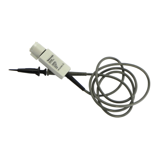
Page 18: Figure 1-1: P6205 Probe With Accessories
Getting Started NOTE. Using the P6205 probe with an 1103 power supply will not add full TEKPROBE functionality to an incompatible oscilloscope. In addition, the 1103 probe offset adjustment does not apply to P6205 probes. 1 Probe head and cable... -
Page 19: Standard Accessories
Getting Started Standard Accessories Table 1–1 lists the P6205 probe standard accessories. Table 1–1: Standard accessories Retractable-hook tip Ground lead with square-pin receptacle Ground lead with alligator clip Ground contact spring Ground sleeve tip cover IC protector tip SMT KlipChip Instruction manual The Replaceable Parts section beginning on page 6–1, contains... - Page 20 Ground +5 V P6205; therefore, the contact pins are omitted from the connector. NOTE. Your oscilloscope may not implement all features of the TEKPROBE interface. Refer to your oscilloscope manual for details.
- Page 21 NOTE: The spring contact installs more easily if you rotate the spring counterclockwise (loosening the spring tension) as you push it onto the probe barrel. Use care to avoid the accidentally shorting of component leads to ground when using this tip. P6205 Instruction Manual 1–5...
- Page 22 Use a ground lead with this accessory. Be sure to take into account ground lead inductance effects on measurements at frequencies approaching 30 MHz. For tips on minimizing ground lead inductance, refer to the Operating Basics section beginning on page 2–1. P6205 Instruction Manual 1–6...
-
Page 23: Grounding The Probe
WARNING. To avoid electric shock when using the probe, keep your fingers behind the finger guard on the probe body. See Figure 1–2 below. Hand contact area Finger guard Figure 1–2: Probe finger guard and hand contact area P6205 Instruction Manual 1–7... - Page 24 Getting Started P6205 Instruction Manual 1–8...
-
Page 25: Operating Basics
Operating Basics... -
Page 27: Ground Lead Inductance
Figure 2–1: Equivalent circuit showing added probe and ground lead resistance, capacitance, and inductance The high input resistance of the P6205 probe has negligible effect on most circuits. The series inductance introduced by the probe tip and ground lead however, can result in a parasitic resonant circuit that “rings”... -
Page 28: Figure 2-2: Effects Of Ground Lead Inductance On Waveform
From this equation, you can see that the desired goal is to lower the probe and ground lead inductance until the frequency of any parasitic oscillation is well beyond the desired frequency of the measurement. The low-inductance ground contact can help reduce the effects of ground lead inductance. P6205 Instruction Manual 2–2... -
Page 29: Linear Operating Range
10 V. Refer to Figure 3–3 on page 3–6 for data on linear operating range. NOTE. The P6205 probe can sustain input voltages to 40 V without damage; however, the linearity error specification does not apply to input voltages exceeding 10 V. -
Page 30: Figure 2-3: P6205 Typical Input Vs Linear Operating Range
2.5 V 7.5 V 10 V Input step (V step) p–p Accurate measuring area Nonlinear area 2.5 V 7.5 V 10 V Input step (V step) p–p Figure 2–3: P6205 typical input vs linear operating range P6205 Instruction Manual 2–4... -
Page 31: Sine Wave Inputs
Degradation of high-amplitude sine wave inputs generally appear as harmonic distortion and reduced peak-to-peak amplitude. Figure 2–4 shows the –3 dB bandwidth of sine wave inputs as a function of amplitude. Amplitude (V sinewave) p–p Figure 2–4: Bandwidth vs sine wave input amplitude P6205 Instruction Manual 2–5... - Page 32 Operating Basics P6205 Instruction Manual 2–6...
-
Page 33: Specifications
Specifications... -
Page 35: Table 3-1: Electrical Characteristics
Specifications This section lists the electrical, environmental, and physical specifications of the P6205 probe. All specifications are guaranteed unless labeled “typical”. Typical specifications are provided for your convenience and are not guaranteed. Specifications marked with the symbol are verified in in the Performance Verification section beginning on page 4–1. - Page 36 Relative to full-scale output with 10 V input: < 4% DC Thermal drift Less than 100 mV/ C For scopes that recognize probe coding: 1 mV on screen Output load requirement 0.5% Maximum nondestructive input voltage 40 VDC + peak AC P6205 Instruction Manual 3–2...
- Page 37 When used with a system having a rise time of less than 100 ps, refer to Aberrations in the Performance Verification section. 11000 Series oscilloscopes only: less than 2 mV following oscilloscope calibration. See page 2–4: Linear Operating Range. At probe output. Less accurate supply levels increase output offset error. P6205 Instruction Manual 3–3...
-
Page 38: Table 3-2: Environmental Characteristics
Table 3–3: Physical characteristics Characteristic Description Shipping weight 0.9 kg (2 lbs) Probe cable length 1.5 m (60 in) tip to BNC Includes accessories. Table 3–4: Certifications and compliances Pollution degree Degree 2 Safety class Class 1 (ground reference) P6205 Instruction Manual 3–4... -
Page 39: Figure 3-1: Typical Input Impedance Vs Frequency
Specifications ohms degrees 100k –25 –50 –75 –100 –125 10kHz 100kHz 1MHz 10MHz 100MHz 1GHz 10GHz Frequency Figure 3–1: Typical input impedance vs frequency 10MHz 100MHz 1GHz 10GHz Frequency Figure 3–2: Voltage derating vs frequency P6205 Instruction Manual 3–5... -
Page 40: Figure 3-3: Linearity Error Vs Output Voltage
– –5mV –10mV –15mV –15/10 –10/10 –5/10 +5/10 +10/10 +15/10 Attenuation Figure 3–3: Linearity error vs output voltage –1 –2 (dB) –3 –4 –5 –6 100kHz 1MHz 10MHz 100MHz 1GHz Frequency Figure 3–4: Typical frequency response P6205 Instruction Manual 3–6... -
Page 41: Performance Verification
Performance Verification... -
Page 43: Test Equipment
Performance Verification This section contains procedures to verify that the P6205 probe meets the performance requirements listed in the Specifications section. The performance verification procedures consists of the following checks: Attenuation Rise Time Aberrations Output offset Performance characteristics not verified by the performance verification procedures are either extremely stable or impractical to verify. -
Page 44: Attenuation Check
BNC, 10 inch length Tektronix part number 012-0208-00 Attenuation Check Use the following procedure to confirm that the P6205 probe performs within its Attenuation specification limits. 1. Set the oscilloscope controls as indicated in the table below. Oscilloscope settings Control... -
Page 45: Figure 4-1: Attenuation Test Setup Part 1
Figure 4–1: Attenuation test setup part 1 3. Press SELECT CHANNEL on the sampling head to enable the corresponding input channel. 4. Adjust the oscilloscope controls as necessary to display a waveform similar to the one shown in Figure 4–2 below. P6205 Instruction Manual 4–3... -
Page 46: Figure 4-2: Calibrator Waveform
9. Connect the P6205 probe output to the 1103 power supply channel 1 input. The P6205 does not use the offset capability of the 1103 power supply; the offset control setting is not important. 10. Mate the GR connector ends of the 50 termination adapter and the male SMA-to-GR adapter. -
Page 47: Rise Time Check
14. Verify that the probe attenuation error is 1.8%. Rise Time Check Use the following procedure to confirm that the P6205 probe performs within its Rise Time specification limits. NOTE. If you do not have access to an 11800 Series oscilloscope, a method for approximating probe rise time using a pulse generator and a TDS 500 or 11000 Series oscilloscope follows this procedure. -
Page 48: Figure 4-5: Rise Time Test Setup
3. Press SELECT CHANNEL on the sampling head to enable the corresponding input channel. 4. Connect the P6205 probe to the 1103 probe power supply channel 1 input. The P6205 does not use the offset capability of P6205 Instruction Manual 4–6... -
Page 49: Rise Time Approximation
5. Mate the GR ends of the male SMA-to-GR and 50 termination adapters. Connect the mated assembly to the oscilloscope calibrator output. Insert the P6205 probe tip firmly into the termination adapter. See Figure 4–5 above. 6. Adjust the oscilloscope horizontal and vertical position controls to display a waveform similar to the one shown in Figure 4–6... -
Page 50: Bandwidth Approximation
BNC-to-GR adapter. Disconnect the coaxial cable at the oscilloscope and attach the mated adapters to the coaxial cable. Connect the P6205 probe to the same oscilloscope input and insert the probe tip firmly into the termination adapter. -
Page 51: Aberrations Check
Performance Verification Aberrations Check Use the following procedure to confirm that the P6205 probe performs within its Aberrations specifications limits. 1. Set the oscilloscope controls as indicated in the table below. Oscilloscope settings Control Setting Volts/division 50 mV Time/division 500 ps... -
Page 52: Figure 4-8: Aberrations Waveform
) in the first 4 ns of the waveform. NOTE. Part one of the aberrations specification applies to the first 20 ns of the waveform. Significant aberrations are usually complete- ly damped beyond approximately 4 ns. P6205 Instruction Manual 4–10... -
Page 53: Figure 4-9: Measuring Aberrations
See Figure 4–10 below. 8. Connect the P6205 probe output to the 1103 power supply channel 1 input. The P6205 does not use the offset capability of the 1103 probe power supply; the offset control setting is not important. -
Page 54: Figure 4-10: Aberrations Test Setup Part 2
(in percent) the probe-plus-system aberrations (abs ) in the first 4 ns of the waveform. Measure the peak negative-going aberration (if any) and the peak positive-going aberration (if any). The sum of the two is the peak-to-peak aberration in percent. P6205 Instruction Manual 4–12... - Page 55 18. Verify that the probe-only aberrations meet specifications: peak, 20 ns to 2 s peak to peak, 20 ns to 2 s P6205 Instruction Manual 4–13...
-
Page 56: Output Offset Check
Performance Verification Output Offset Check Use the following procedure to confirm that the P6205 probe performs within its Output Offset specification limits. 1. Set the oscilloscope controls as indicated in the table below. Oscilloscope settings Control Setting Volts/division 2 mV... - Page 57 Maintenance...
-
Page 59: Preventive Maintenance
The best indicator of probe condition is performance. In addition to performing the performance verification procedures, occasionally inspect the probe tip, body, cable, compensation box, and BNC connector for bent, broken, or damaged parts. To ensure optimum performance, replace damaged assemblies as soon as practical. P6205 Instruction Manual 5–1... -
Page 60: Cleaning
To guarantee probe performance, do not attempt to replace the individual components of replaceable assemblies. WARNING. To prevent electric shock, disconnect the probe from the signal source and oscilloscope or power supply before performing preventive maintenance. P6205 Instruction Manual 5–2... -
Page 61: Static Sensitive Devices
Maintenance Static Sensitive Devices The P6205 probe contains devices that are susceptible to damage from static discharge. To prevent damage to static-sensitive devices, observe the following precautions whenever the compensation box covers are removed or you are handling component assemblies: Minimize the handling of all components;... -
Page 62: Replacing Internal Assemblies: Probe Head And Cable, Bnc And Circuit Board Carrier
Probe Disassembly. Refer to Figure 5–1 and use the following procedure to disassemble the P6205 probe. 1. Use a small, flat screwdriver (or the optional compensation box release tool) to pry the compensation box cover slots off the tabs that secure it to the compensation box base. -
Page 63: Figure 5-1: Disassembling The P6205 Probe
Maintenance Figure 5–1: Disassembling the P6205 probe Probe Resassembly. Refer to Figure 5–1 and use the following procedure to reassemble the P6205 probe. 1. Verify that the center conductor of the probe cable is straight and centered in its connector; the center conductor must align with a receptacle seated deeply within the BNC and circuit board carrier assembly. -
Page 64: Readjustment Following Repair
2. Surround the probe with protective polyethylene sheeting. 3. Cushion the probe on all sides with at least two inches of tightly packed urethane foam or other packing material. 4. Seal the carton with shipping tape or an industrial stapler. P6205 Instruction Manual 5–6... -
Page 65: Replaceable Parts
Replaceable Parts... -
Page 67: Parts Ordering Information
Replaceable Parts This section contains a list of the replaceable modules for the P6205 probe. Use this list to identify and order replacement parts. Parts Ordering Information Replacement parts are available through your local Tektronix field office or representative. Changes to Tektronix products are sometimes made to accommodate improved components as they become available and to give you the benefit of the latest improvements. -
Page 68: Using The Replaceable Parts List
Using the Replaceable Parts List This section contains a list of the mechanical and or electrical components that are replaceable for the P6205 probe. Use this list to identify and order replacement parts. The following table describes each column in the parts list. -
Page 69: Abbreviations
PO BOX 500 97077–0001 8X345 NORTHWEST SPRING MFG 5858 WILLOW LANE LAKE OSWEGO, OR 97035 TK2548 XEROX CORPORATION 14181 SW MILLIKAN WAY BEAVERTON, OR 97005 TK2565 VISION PLASTICS INC 26000 SW PARKWAY WILSONVILLE, OR 97070 CENTER DRIVE P6205 Instruction Manual 6–3... -
Page 70: Figure 6-1: P6205 Probe With Standard Accessories
Figure 6–1: P6205 probe with standard accessories... - Page 71 Replaceable parts: P6205 probe and standard accessories Fig. & Tektronix Serial no. Serial no. index part number effective discont’d number Name & description Mfr. code Mfr. part number 6–1 –1 013–0107–06 TIP,PROBE:MINIATURE/COMPACT 80009 013–0107–06 SIZE,RETRACTABLE HOOK ASSY –2 131–4280–00 CONTACT,ELEC:PROBE TIP 80009 131–4280–00...
- Page 72 Replaceable Parts P6205 Instruction Manual 6–6...
- Page 73 Replaceable parts: P6205 probe optional accessories Fig. & Tektronix Serial no. Serial no. index part number effective discont’d number Name & description Mfr. code Mfr. part number OPTIONAL ACCESSORIES 6–2 –1 003–1383–00 RLSE TOOL,COVER:COMP BOX,POLYCARBONATE TK2565 003–1383–00 –2 003–1433–00 SCREWDRIVER:ADJUSTMENT TOOL,METAL TIP TK2565 003–1433–00...
- Page 74 Replaceable Parts P6205 Instruction Manual 6–8...
Need help?
Do you have a question about the P6205 and is the answer not in the manual?
Questions and answers