Table of Contents
Advertisement
Quick Links
Instruction Manual
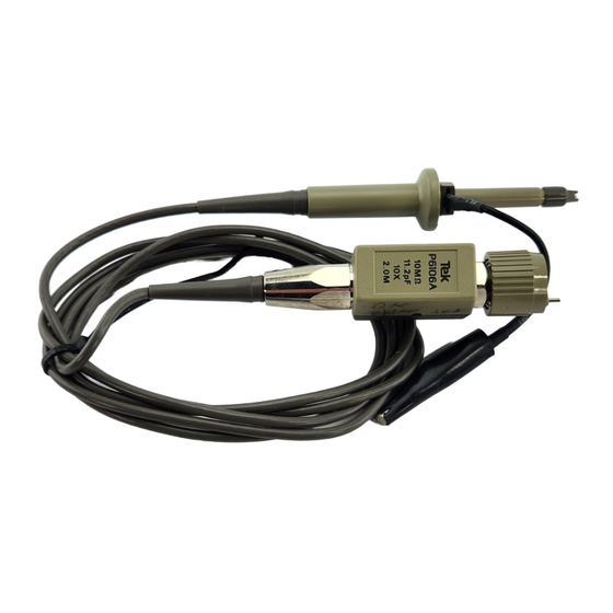
P6106A
250 MHz 10X Passive Probe
070-5517-03
Warning
The servicing instructions are for use by qualified
personnel only. To avoid personal injury, do not
perform any servicing unless you are qualified to
do so. Refer to all safety summaries prior to
performing service.
www.tektronix.com
070551703
Advertisement
Table of Contents

Related Manuals for Tektronix P6106A


Summary of Contents for Tektronix P6106A
- Page 1 Instruction Manual P6106A 250 MHz 10X Passive Probe 070-5517-03 Warning The servicing instructions are for use by qualified personnel only. To avoid personal injury, do not perform any servicing unless you are qualified to do so. Refer to all safety summaries prior to performing service.
- Page 2 Copyright Tektronix, Inc. All rights reserved. Tektronix products are covered by U.S. and foreign patents, issued and pending. Information in this publication supercedes that in all previously published material. Specifications and price change privileges reserved. Tektronix, Inc., P.O. Box 500, Beaverton, OR 97077...
- Page 3 Tektronix, shipping charges prepaid, and with a copy of customer proof of purchase. Tektronix shall pay for the return of the product to Customer if the shipment is to a location within the country in which the Tektronix service center is located.
-
Page 4: Contacting Tektronix
6:00 a.m. – 5:00 p.m. Pacific time Or contact us by e-mail: tm_app_supp@tek.com For product support outside of North America, contact your local Tektronix distributor or sales office. Service Tektronix offers extended warranty and calibration programs as options on many support products. -
Page 5: General Safety Summary
Keep Product Surfaces Clean and Dry. Symbols and Terms Terms in this Manual. The following terms may appear in this manual: WARNING. Warning statements identify conditions or practices that could result in injury or loss of life. P6106A Instruction Manual... -
Page 6: Service Safety Summary
Safety Summary and the General Safety Summary before performing any service procedures. Do Not Service Alone. Do not perform internal service or adjustments to this product unless another person capable of rendering first aid and resuscitation is present. P6106A Instruction Manual... -
Page 7: P6106A Passive Probe
P6106A Passive Probe Thank you for choosing a Tektronix passive probe. This manual provides the information necessary to begin making measurements with your P6106A probe. Topics are presented in the following order: Description—A description of the probe and its options. -
Page 8: Installation
Accessories This instruction manual—Read these instructions to familiarize yourself with he features, specifications, and operation of the P6106A passive probe. Accessory pouch—(not shown) Use the accessory pouch to store the probe and its accessories when they are not being used. - Page 9 P6106A Passive Probe reason.To make probe identification easy, clip matching colored rings onto the probe cable and tip as shown. Three-inch ground lead—Use the Three-inch ground lead to establish a ground reference for your measurements. Whenever freedom from aberra- tions and amplitude accuracy are more important than probe reach and flexibility, use the shortest ground lead possible.
-
Page 10: Operating Considerations
P6106A Passive Probe Operating Considerations This information in this section will help you make the most effective use of your P6106A probe. Features and Controls Readout pin—The BNC connector of the probe includes a spring-loaded pin that connects to a mating contact ring on certain oscilloscopes. These oscilloscopes recognize the attenuation factor of the probe and automatically correct the oscilloscope indication of scale factor. -
Page 11: Low-Frequency Probe Compensation
P6106A Passive Probe A passive probe is capacitive for high-frequency signals. For most circuits, the high input resistance of a passive probe has a negligible effect on the signal. The series inductances represented by the probe tip and ground lead, however, can result in a parasitic resonant circuit that may “ring”... - Page 12 P6106A Passive Probe 2. Press AUTOSET (on many Tektronix oscilloscopes) or otherwise adjust the oscilloscope so that it displays a waveform similar to those shown in this section. Optional: If your oscilloscope has a limited-bandwidth mode, enable it. Filtering out high-frequency noise will make the adjustment easier to perform.
- Page 13 P6106A Passive Probe NOTE. We strongly recommend that you use the optional probe tip-to-BNC adapter (Tektronix part number 013-0084-04) to connect your probe to the signal source. 1. Remove the covers from the probe compensation box by gently prying them off with a fingernail or small screwdriver.
-
Page 14: Specifications
1000 V peak, @20% DF, <1 sec PW 1050 V peak, @10% DF, <50 s PW See Figure 7 for voltage derating curve. Probe installed on Tektronix 475A/7A26 or equivalent 250 MHz oscilloscope. System characteristic. As defined in EN61010-1. See Certifications and compliances in Table 3... - Page 15 P6106A Passive Probe @25% Duty Factor =(1/2 Peak V) RMS @50% Duty Factor =(1.414 (Peak V)) RMS Special case of square wave: @20% Duty Factor =[(V (Duty Factor)] Peak Example: Maximum Input Voltage =[(1000 V Pk) (.20)] = 450 V RMS...
- Page 16 P6106A Passive Probe Figure 7: Derating Curve for Determining Maximum Input Voltage Table 2: Physical and Environmental Characteristics Characteristic Performance Requirement Net Weight <110 g (0.24 lbs) (including accessories) Temperature Range Operating –15 C to +65 C (+5 F to +149 F) Nonoperating –62 C to +85 C (–80 F to +185 F)
-
Page 17: Maintenance
P6106A Passive Probe Table 3: Certifications and compliances (Cont.) Overvoltage Category: Examples of Products in this Category: Category CAT III Distribution-level mains, fixed installation CAT II Local-level mains, appliances, portable equipment CAT I Signal levels in special equipment or parts of... - Page 18 Probe Cable Compensation Box Probe Head Figure 8: P6106A Replaceable Modules Probe head—To remove the probe head, simply pull it free from the cable. To reinstall the probe head, push the cable end into the head until the connector snaps into place.
-
Page 19: Replaceable Parts
P6106A Passive Probe Replaceable Parts Figure 9: P6106A Exploded View Replaceable mechanical parts list Fig. & Tektronix part Serial no. Serial no. Mfr. index number effective discont’d code number Name & description Mfr. part number P6106A 9– PROBE,PASSIVE250 MHZ,10X W/RO 2M... - Page 20 P6106A Passive Probe Replaceable mechanical parts list (Cont.) Fig. & Tektronix part Serial no. Serial no. Mfr. index number effective discont’d code number Name & description Mfr. part number –8 206–0301–00 .PROBE HEAD:2.0 METER 80009 206–0301–00 .(STANDARD ONLY) 206–0328–00 .PROBE HEAD:1.0 METER CABLES,H951 80009 206–0328–00...
Need help?
Do you have a question about the P6106A and is the answer not in the manual?
Questions and answers