Sign In
Upload
Download
Table of Contents
Contents
Add to my manuals
Delete from my manuals
Share
URL of this page:
HTML Link:
Bookmark this page
Add
Manual will be automatically added to "My Manuals"
Print this page
×
Bookmark added
×
Added to my manuals
Manuals
Brands
Tektronix Manuals
Measuring Instruments
P6250
User manual
Tektronix P6250 User Manual
500 mhz and 1 ghz high voltage differential probes
Hide thumbs
1
2
3
4
Table Of Contents
5
6
7
8
9
10
11
12
13
14
15
16
17
18
19
20
21
22
23
24
25
26
27
28
29
30
31
32
33
34
35
36
37
38
39
40
41
42
43
44
45
46
47
48
49
50
51
52
53
54
55
56
57
58
59
60
61
page
of
61
Go
/
61
Contents
Table of Contents
Bookmarks
Table of Contents
Table of Contents
General Safety Summary
Environmental Considerations
Preface
Documentation
Conventions Used in this Manual
Returning the Probe for Servicing
Key Features
Operating Considerations
Installation
Connecting to the Host Instrument
Probe Controls
Functional Check
Required Equipment
Calibration
Prerequisites
Required Equipment
Test Procedure
Basic Operation
Probe Head Assembly
Probe Input
Probe Offset
Applications
Accessories and Options
Using Standard Accessories
Optional Accessories
Options
Probing Principles
Probe Grounding
Input Impedance and Probe Loading
Maintenance
Replacement Parts
Cleaning
Index
Advertisement
Quick Links
Download this manual
P6250 and P6251
xx
500 MHz and 1 GHz High Voltage Differential Probes
ZZZ
Quick Start User Manual
www.tektronix.com
071-2429-00
Table of
Contents
Previous
Page
Next
Page
1
2
3
4
5
Advertisement
Table of Contents
Need help?
Do you have a question about the P6250 and is the answer not in the manual?
Ask a question
Questions and answers
Related Manuals for Tektronix P6250
Measuring Instruments Tektronix P6243 Instructions Manual
1 ghz 10x active probe (34 pages)
Measuring Instruments Tektronix P6248 Instructions Manual
Differential probe (40 pages)
Measuring Instruments Tektronix P6248 Service Manual
1.7 ghz typical differential probe (58 pages)
Measuring Instruments Tektronix P6231 Manual
(64 pages)
Measuring Instruments Tektronix P6231 Instruction Manual
(63 pages)
Measuring Instruments Tektronix P6205 Instruction Manual
Fet probe (74 pages)
Measuring Instruments Tektronix P6209 Instruction Manual
4 ghz 5x active probe (75 pages)
Measuring Instruments Tektronix P6202A Instruction Manual
10x, 500mhz fet probe (108 pages)
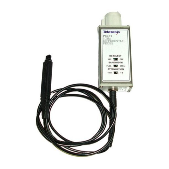
Measuring Instruments Tektronix P6251 User Manual
500 mhz and 1 ghz high voltage differential probes (61 pages)
Measuring Instruments Tektronix P6204 Instruction Manual
Fet probe, 10m ohm, 10x, id (69 pages)
Measuring Instruments Tektronix P6207 Instruction Manual
Fet probe (85 pages)
Measuring Instruments Tektronix P6241 Instruction Manual
4.0 ghz 10x active probe zzz (89 pages)
Measuring Instruments Tektronix P6201 Instruction Manual
(36 pages)
Measuring Instruments Tektronix P6202 Instruction Manual
Probe with options (89 pages)
Measuring Instruments Tektronix P6330 Instruction Manual
Differential probe (81 pages)
Measuring Instruments Tektronix P6015 Instruction Manual
(26 pages)
This manual is also suitable for:
P6251
Table of Contents
Print
Rename the bookmark
Delete bookmark?
Delete from my manuals?
Login
Sign In
OR
Sign in with Facebook
Sign in with Google
Upload manual
Upload from disk
Upload from URL


Need help?
Do you have a question about the P6250 and is the answer not in the manual?
Questions and answers