Table of Contents
Advertisement
Quick Links
Instruction Manual
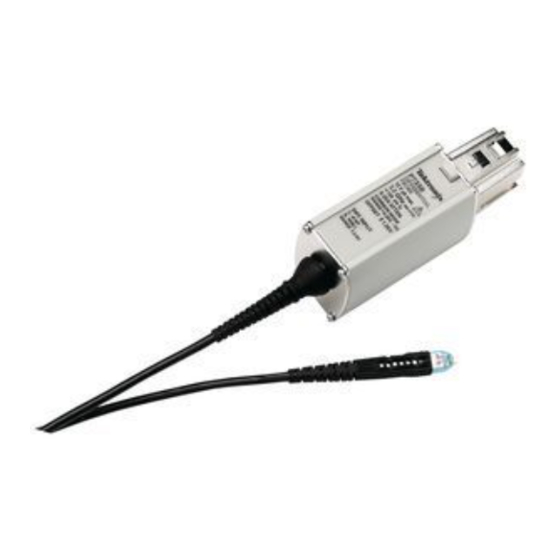
P6330
3.5 GHz Differential Probe
071-0757-04
Warning
The servicing instructions are for use by qualified
personnel only. To avoid personal injury, do not
perform any servicing unless you are qualified to
do so. Refer to all safety summaries prior to
performing service.
www.tektronix.com
Advertisement
Table of Contents

Related Manuals for Tektronix P6330


Summary of Contents for Tektronix P6330
- Page 1 Instruction Manual P6330 3.5 GHz Differential Probe 071-0757-04 Warning The servicing instructions are for use by qualified personnel only. To avoid personal injury, do not perform any servicing unless you are qualified to do so. Refer to all safety summaries prior to performing service.
- Page 2 Copyright © Tektronix, Inc. All rights reserved. Tektronix products are covered by U.S. and foreign patents, issued and pending. Information in this publication supercedes that in all previously published material. Specifications and price change privileges reserved. Tektronix, Inc., P.O. Box 500, Beaverton, OR 97077 TEKTRONIX, TEK, TEKPROBE, and SureFoot are registered trademarks of Tektronix, Inc.
- Page 3 Tektronix, with shipping charges prepaid. Tektronix shall pay for the return of the product to Customer if the shipment is to a location within the country in which the Tektronix service center is located. Customer shall be responsible for paying all shipping charges, duties, taxes, and any other charges for products returned to any other locations.
-
Page 5: Table Of Contents
......... Instruments with the TEKPROBE Interface (Tektronix TDS 400, 500, 600, and 700 Series Oscilloscopes) . - Page 6 ........P6330 3.5 GHz Differential Probe Instruction Manual...
- Page 7 ....Figure 32: P6330 optional accessories ....P6330 3.5 GHz Differential Probe Instruction Manual...
- Page 8 Table of Contents P6330 3.5 GHz Differential Probe Instruction Manual...
-
Page 9: General Safety Summary
Do Not Operate With Suspected Failures. If you suspect there is damage to this product, have it inspected by qualified service personnel. Do Not Operate in Wet/Damp Conditions. Do Not Operate in an Explosive Atmosphere. Keep Product Surfaces Clean and Dry. P6330 3.5 GHz Differential Probe Instruction Manual... - Page 10 WARNING indicates an injury hazard not immediately accessible as you read the marking. CAUTION indicates a hazard to property including the product. Symbols on the Product. These symbols may appear on the product: CAUTION Refer to Manual P6330 3.5 GHz Differential Probe Instruction Manual...
-
Page 11: Service Safety Summary
Service Safety Summary and the General Safety Summary before performing any service procedures. Do Not Service Alone. Do not perform internal service or adjustments of this product unless another person capable of rendering first aid and resuscitation is present. P6330 3.5 GHz Differential Probe Instruction Manual... -
Page 12: Contacting Tektronix
This phone number is toll free in North America. After office hours, please leave a voice mail message. Outside North America, contact a Tektronix sales office or distributor; see the Tektronix web site for a list of offices. P6330 3.5 GHz Differential Probe Instruction Manual viii... -
Page 13: Product Features And Accessories
Product Features and Accessories The P6330 is a high-bandwidth (3.5 GHz) active differential probe with a miniaturized probe head design. The probe has low circuit loading, high common-mode rejection, and comes with a variety of accessories for connecting to surface-mount devices and other components. -
Page 14: Options
Product Features and Accessories Options The following options are available when ordering the P6330 probe: H Option D1 - - Calibration Data H Option C3 - - 3 years Calibration Service H Option D3 - - 3 years Calibration Data (requires Option C3) H Option R3 - - 3 years Extended Warranty P6330 3.5 GHz Differential Probe Instruction Manual... -
Page 15: Features And Standard Accessories
Product Features and Accessories Features and Standard Accessories Table 1 shows the features and standard accessories of the P6330 differential probe. Table 1: P6330 features and standard accessories Feature/Accessory Description TEKPROBE interface. The TEKPROBE interface supplies power to the probe, selects the correct display scaling, and automatically sets the 50 Ω... - Page 16 Product Features and Accessories Table 1: P6330 features and standard accessories (Cont.) Feature/Accessory Description Variable spacing adapter (4 ea). The variable spacing adapter fits over the probe tip. Push the adapter onto the probe tip until it seats against the probe head.
- Page 17 Product Features and Accessories Table 1: P6330 features and standard accessories (Cont.) Feature/Accessory Description TwinFoot adapter (4 ea). Use the TwinFoot adapter to probe two adjacent leads on a surface-mount integrated circuit. The TwinFoot adapter connects to the probe through the square pin adapter.
- Page 18 Product Features and Accessories Table 1: P6330 features and standard accessories (Cont.) Feature/Accessory Description Plastic accessory box. Use the plastic box to store the probe accessories when not in use. Tektronix part number: 006-7164-00 Instrument case. The instrument case protects the probe from harsh environments and provides room for storing optional accessories.
-
Page 19: Optional Accessories
TEKPROBE Interface. Power cord options are available for the following countries or regions. Standard. North America and Japan Option A1. European Option A2. UK Option A3. Australia Option A5. Switzerland P6330 3.5 GHz Differential Probe Instruction Manual... - Page 20 50 Ω termination. Terminates the output of the 1103 power supply to the required 50 Ω if the oscilloscope does not have a 50 Ω input setting. Order Tektronix part number 011-0049-01. 50 Ω BNC cable. Connects to the 1103 output.
-
Page 21: Operating Basics
(CMRR), see the Reference section on page 19. The P6330 probe design is optimized for high bandwidth, low capacitance applications; it is not a general purpose probe. The probe head and tips are miniaturized for electrical characteristics and access to dense circuitry, and must be handled carefully. -
Page 22: Instruments With The Tekprobe Interface (Tektronix Tds 400, 500, 600, And 700 Series Oscilloscopes)
NOTE. TDS 400 and TDS 400A series oscilloscopes do not interpret the scale factor coding of the P6330 differential probe. To correct for this problem, divide the measurement (or scale factor) by 5. Instruments without the TEKPROBE Interface On instruments that do not have the TEKPROBE interface, you must order the optional 1103 power supply (refer to page 7). -
Page 23: Maximum Input Voltage
CAUTION. To avoid damaging the inputs of the P6330 differential probe, do not apply more than ± 15 V (DC + peak AC) between each input and ground. -
Page 24: Probing Techniques To Maximize Cmrr
Figure 3: Using the variable spacing adapter IC leads being probed TwinFoot adapter Square pin adapter Conductive side of probe tip Probe Insulated side of probe tip Figure 4: Using the TwinFoot adapter P6330 3.5 GHz Differential Probe Instruction Manual... -
Page 25: Electrical Effects Of Accessories
The recommended method for hands-free probing is to use the probe only (without adapters), with a probe positioner such as a Tektronix PPM203B. If you need a tip space between 0.020 and 0.180 inches apart, use the variable spacing adapter and the probe positioner. Use the square pin adapter for test points or component leads spaced farther than 0.180 inches apart. -
Page 26: Input Impedance And Probe Loading
When you connect the probe inputs to a circuit, you are introducing a new resistance, capacitance, and inductance into the circuit. Each input of the P6330 differential probe has a characteristic input impedance of 50 kΩ to ground in parallel with less than 0.4 pF. See Figure 6. -
Page 27: Probe Grounding
There are some applications that may require a ground reference connection to maintain measurement accuracy. Generally this is necessary when probing circuits which are fully isolated from ground, such as battery operated devices. P6330 3.5 GHz Differential Probe Instruction Manual... - Page 28 Operating Basics P6330 3.5 GHz Differential Probe Instruction Manual...
-
Page 29: Functional Check
Y-lead adapter to the square pin adapter. Plug the SMT KlipChips into the Y-lead adapter. 4. Connect the SMT KlipChips to the PROBE COMPENSATION connections on the oscilloscope. 5. Adjust the oscilloscope to display a stable calibration waveform. P6330 3.5 GHz Differential Probe Instruction Manual... - Page 30 7. With the probe offset set to 0.0 V, the oscilloscope display should be at the ground reference. 8. Set the oscilloscope volts/division to 500 mV. 9. Adjust the probe offset. The displayed waveform should vary between approximately +1.0 V and - - 1.0 V. P6330 3.5 GHz Differential Probe Instruction Manual...
-
Page 31: Reference
Voltage that is common to both inputs is often referred to as the Common-Mode Voltage (V ) and voltage that is different as the Differential-Mode Voltage (V P6330 3.5 GHz Differential Probe Instruction Manual... -
Page 32: Common-Mode Rejection Ratio
CMRR generally is highest (best) at DC and degrades with increasing frequency. Assessing CMRR Error Figure 11 on page 28 shows the CMRR of the P6330 differential probe. This derating chart assumes a common-mode signal that is sinusoidal. P6330 3.5 GHz Differential Probe Instruction Manual... -
Page 33: Input Impedance Effects On Cmrr
Figure 10. Twisting the input leads together does increase capacitance that may degrade high-frequency performance. You should take into account any effects caused by the extended leads when you take a measure- ment. P6330 3.5 GHz Differential Probe Instruction Manual... -
Page 34: Extending The Ground Lead
50 Ω. If the measurement instrument does not support 50 Ω input termination, connect a 50 Ω coaxial terminator on the input. P6330 3.5 GHz Differential Probe Instruction Manual... -
Page 35: Effect Of Extending The Output Cable
As the frequency of a signal increases, current flow concentrates at the outer edges of the conductor, effectively increasing the impedance. This effect is known as skin loss. The P6330 probe contains circuitry to compensate for skin loss. The compensation provides flat response with the probe cable. - Page 36 Reference P6330 3.5 GHz Differential Probe Instruction Manual...
-
Page 37: Specifications
Specifications The specifications in Tables 3 through 6 apply to a P6330 probe installed on a TDS8000 oscilloscope. When the probe is used with another oscilloscope, the oscilloscope must have an input impedance of 50 Ω. The probe must have a warm-up period of at least 20 minutes and be in an environment that does not exceed the limits described in Table 3. -
Page 38: Typical Characteristics
± 1% or less of dynamic range Linearity Common-mode signal range + 5 V to --4 V ≥60 dB at DC Common-mode rejection ratio ≥55 dB at 1 MHz ≥45 dB at 30 MHz ≥25 dB at 1 GHz P6330 3.5 GHz Differential Probe Instruction Manual... - Page 39 2% of input voltage offset gain error = 2% of effective offset at probe tip output zero = 50 mV effective at probe tip linearity error = 1.0% of 4.0 V dynamic range (40.0 mV) P6330 3.5 GHz Differential Probe Instruction Manual...
-
Page 40: Figure 11: Typical Common-Mode Gain
The graph in Figure 12 represents simulation results of a first order model of the probe input. Impedance (Ω) 100 k 10 k 10 M 100 M Frequency (Hz) Figure 12: Typical differential input impedance vs frequency P6330 3.5 GHz Differential Probe Instruction Manual... -
Page 41: Figure 13: Probe Head And Compensation Box Dimensions
1.3 m (51 in) Unit weight (probe only) 160 g (5.4 oz) 1.1 in 0.3 in 2.3 in 0.9 in 0.2 in 0.1 in 3.2 in Figure 13: Probe head and compensation box dimensions P6330 3.5 GHz Differential Probe Instruction Manual... -
Page 42: Nominal Characteristics
Nominal characteristics (Table 6) describe guaranteed traits, but the traits do not have tolerance limits. Table 6: Nominal electrical characteristics Input configuration Differential (two inputs, + and -- ), with case ground Attenuation Input coupling Terminate output into 50 Ω Termination P6330 3.5 GHz Differential Probe Instruction Manual... - Page 43 WARNING The following servicing instructions are for use only by qualified personnel. To avoid injury, do not perform any servicing other than that stated in the operating instructions unless you are qualified to do so. Refer to all safety summaries before performing any service.
-
Page 45: Theory Of Operation
Zero - - offset Probe Tip Offset IN - - Gain +7 V Linear +15 V regulator +5 V - - 5 V Ground Probe TEKPROBE Cable Interface Figure 14: Simplified schematic diagram P6330 3.5 GHz Differential Probe Instruction Manual... -
Page 46: Probe Head And Cable Assembly
Probe Identification EEPROM The probe identification EEPROM is used to configure the oscilloscope to the probe. The EEPROM receives a clock input from the oscilloscope, and information about the probe is passed to the oscilloscope. P6330 3.5 GHz Differential Probe Instruction Manual... -
Page 47: Tekprobe Interface
Figure 15 shows the TEKPROBE interface pin functions. Refer to the service documenation for your oscilloscope for more detailed specifications. - - 15 V - - 5 V Offset Ground Signal Data Clock +5 V +15 V Figure 15: TEKPROBE interface P6330 3.5 GHz Differential Probe Instruction Manual... - Page 48 Theory of Operation P6330 3.5 GHz Differential Probe Instruction Manual...
-
Page 49: Performance Verification
Performance Verification Use the following procedures to verify specifications of the P6330 probe. Before beginning these procedures, refer to page 46 and photocopy the test record, and use it to record the performance test results. The recommended calibration interval is one year. -
Page 50: Equipment Setup
Use this procedure to set up the equipment to test the probe. 1. Connect the probe to the 1103 power supply. 2. Turn on 1103 power supply. 3. Turn on the oscilloscope. 4. Allow 20 minutes for the equipment to warm up. P6330 3.5 GHz Differential Probe Instruction Manual... -
Page 51: Probe Calibration Fixture
The fixture is designed to be used with a probe positioner, such as a Tektronix PPM203B. Figure 16: Probe Calibration Fixture Using the Probe Calibration Fixture 1. -
Page 52: Figure 17: Probe Calibration Fixture Test Points
6. Verify that contact is made on both pins. (You may need to readjust the fine position and/or pressure adjustment to make positive contact with the test points.) 7. Proceed with the specific test instructions. P6330 3.5 GHz Differential Probe Instruction Manual... -
Page 53: Output Offset Voltage
1. Connect the probe input to the DC source, as shown in Figure 19 on page 42. Monitor the source voltage with the DMM. 2. Set the input voltage on the DC source to approximately +0.5 V. Record the actual voltage as V P6330 3.5 GHz Differential Probe Instruction Manual... -
Page 54: Figure 19: Dc Gain Accuracy Setup
Record the actual voltage as V 5. Record the output voltage as V ÷ 6. Calculate the gain as follows: (V 1 - - V 1 - - V 7. Verify that the gain is 0.2, ± 2%. P6330 3.5 GHz Differential Probe Instruction Manual... -
Page 55: Rise Time
7. Use the oscilloscope measurement capability to display rise time. Rise time is determined from the 10% and 90% amplitude points on the waveform. Record the rise time as t P6330 3.5 GHz Differential Probe Instruction Manual... -
Page 56: Figure 21: Test System Rise Time Setup With Probe
BNC-to-SMA adapter CH 1 CH 1 015-0572-00 output input SD24/ 80E04 Oscilloscope SMA cable 1103 015-0562-00 Probe cal fixture SMA cable 067-0419-00 174-1427-00 P6330 Figure 21: Test system rise time setup with probe P6330 3.5 GHz Differential Probe Instruction Manual... -
Page 57: Figure 22: Verifying Both Probe Pins Are Contacting The Dm Test Points
Record the rise time as t s+p. 16. Calculate the probe rise time using the following formula: − t (s+p) 17. Record the calculated probe rise time on the test record. P6330 3.5 GHz Differential Probe Instruction Manual... - Page 58 Performance test Minimum Incoming Outgoing Maximum -- 10 mV ________ ________ + 10 mV Output offset voltage DC gain accuracy -- 2 % ________ ________ + 2 % ≤140 ps Rise time ________ ________ P6330 3.5 GHz Differential Probe Instruction Manual...
-
Page 59: Adjustments
Adjustments The P6330 has 3 internal controls: offset zero, offset range, and DC CMRR. These controls should only be adjusted after a probe performance verification and functional check has been performed on the oscilloscope, and only if a check fails to meet its specifica- tion. -
Page 60: Removing The Compensation Box Cover
2. Hold the open edge apart, and use the tool to open the other side of the compensation box. 3. With both sides of the box open, gently separate the two halves of the compensation box. Release tool Cover catches Figure 23: Removing the compensation box cover P6330 3.5 GHz Differential Probe Instruction Manual... -
Page 61: Figure 24: Adjustment And Test Point Locations
Offset zero Connector test points CMRR Blk - - CMRR Blu - - Offset Offset range Wht - - 5V Red + 7V Figure 24: Adjustment and test point locations P6330 3.5 GHz Differential Probe Instruction Manual... -
Page 62: Offset Zero And Dc Cmrr
4. Adjust Offset Zero for 0.00 V ±3 mV, displayed on the DMM. Record the actual value. 5. Connect the probe as shown in Figure 25 on page 51. Monitor the source voltage with the DMM. P6330 3.5 GHz Differential Probe Instruction Manual... -
Page 63: Figure 25: Offset Zero And Dc Cmrr Setup
9. Record the output voltage as V 10. Set the input voltage on the DC source to approximately - - 3.0 V. Record the actual voltage as V 11. Record the output voltage as V P6330 3.5 GHz Differential Probe Instruction Manual... - Page 64 3). If the offset voltage magnitude is greater than 3.0 mV, or if the CMRR is less than 60 dB, disconnect the probe from the test circuit. Repeat the procedure, beginning with step 1 on page 50, to compensate for the adjustment interaction. P6330 3.5 GHz Differential Probe Instruction Manual...
-
Page 65: Offset Range
5. Observe the DC value on the DMM connected to the 1103 power supply. Digital multimeter 1103 Power supply Power supply KlipChip 50 Ω Precision adapters terminator Square-pin adapter BNC-to-dual Y-lead adapter Banana adapter P6330 Probe Figure 26: P6330 offset range setup P6330 3.5 GHz Differential Probe Instruction Manual... -
Page 66: Replacing The Compensation Box Cover
2. Press the cover catches in so that the cover can be lowered. 3. Slide the tab into the notch. 4. Firmly press the pieces together until the cover catches snap into place. Figure 27: Replacing the compensation box cover P6330 3.5 GHz Differential Probe Instruction Manual... -
Page 67: Maintenance
If necessary, seat the pin into the connector by pressing the tip gently but firmly against a hard surface, such as a wood block or table top. Figure 28: Replacing TEKPROBE interface pins P6330 3.5 GHz Differential Probe Instruction Manual... -
Page 68: Removing And Replacing The Tekprobe Interface Collar
Align the tab to the slot, and gently press the two pieces together. See Figure 29. Once installed, the TEKPROBE collar should rotate freely to lock and unlock. Slot Figure 29: Replacing the TEKPROBE interface collar P6330 3.5 GHz Differential Probe Instruction Manual... -
Page 69: Inspection And Cleaning
Replacement Parts Refer to the Replaceable Parts section for a list of customer replacement parts. Due to the sophisticated design of the P6330, there are no user replaceable parts within the probe. Preparation for Shipment... - Page 70 Maintenance P6330 3.5 GHz Differential Probe Instruction Manual...
-
Page 71: Replaceable Parts
Replaceable Parts This section contains a list of replaceable parts for the P6330 differential probe. Use this list to identify and order replacement parts. Parts Ordering Information Replacement parts are available from or through your local Tektronix, Inc. service center or representative. -
Page 72: Using The Replaceable Parts List
Indented items are part of, and included with, the next higher indentation. Attaching parts must be purchased separately, unless otherwise specified. Abbreviations Abbreviations conform to American National Standards Institute (ANSI) standard Y1.1 P6330 3.5 GHz Differential Probe Instruction Manual... -
Page 73: Figure 30: P6330 Replaceable Parts
Replaceable Parts P6330 3.5 GHz Differential Probe Instruction Manual... - Page 74 Replaceable Parts P6330 3.5 GHz Differential Probe Instruction Manual...
-
Page 75: Figure 31: P6330 Standard Accessories
Replaceable Parts P6330 3.5 GHz Differential Probe Instruction Manual... - Page 76 Replaceable Parts P6330 3.5 GHz Differential Probe Instruction Manual...
-
Page 77: Figure 32: P6330 Optional Accessories
Replaceable Parts P6330 3.5 GHz Differential Probe Instruction Manual... - Page 78 Replaceable Parts P6330 3.5 GHz Differential Probe Instruction Manual...
- Page 79 Replaceable Parts P6330 3.5 GHz Differential Probe Instruction Manual...
- Page 80 Replaceable Parts P6330 3.5 GHz Differential Probe Instruction Manual...
- Page 81 Mouser Electronics Authorized Distributor Click to View Pricing, Inventory, Delivery & Lifecycle Information: Tektronix P6330...
Need help?
Do you have a question about the P6330 and is the answer not in the manual?
Questions and answers