
Subscribe to Our Youtube Channel
Related Manuals for Intel JBOD2312S3SP


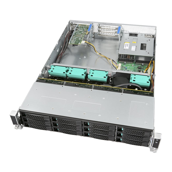
Summary of Contents for Intel JBOD2312S3SP
- Page 1 Intel ® Storage System JBOD2312S3SP Hardware Guide A document providing a system level overview of product features, functions, architecture, and support specifications Revision 1.3 Mar 2016 Intel® Server Boards and Systems...
- Page 2 <This page is intentionally left blank.>...
- Page 4 JBOD2000S3SP Hardware Guide Revision History Revision Date Modifications Number November 2014 Pre-production release. December 2014 Production version release. May 2015 Removed references to PSU Cold Redundancy support. October 2015 Added optional PSU and power cable references in the Power Subsystem section.
- Page 5 This document contains information on products, services and/or processes in development. All information provided here is subject to change without notice. Contact your Intel representative to obtain the latest Hardware Guide.
-
Page 6: Table Of Contents
Intel® Storage Server System JBOD2312S3SP Hardware Guide Table of Contents Introduction .................................. 1 Server Product Use Disclaimer ............................... 1 Product Errata ....................................1 Product Family Overview ............................2 Chassis Dimensions ..................................3 System Level Environmental Limits ............................4 System Features and Options Overview ..........................5 2.3.1... - Page 7 Intel® Storage Server System JBOD2312S3SP Hardware Guide 4.6.17 Over Temperature Protection (OTP) ........................21 Power Supply Status LED ..............................21 Thermal Management ............................. 23 Thermal Operation and Configuration Requirements ....................23 Thermal Management Overview ............................23 Thermal Sensor Input for Fan Speed Control ........................ 23 System Fans ....................................
- Page 8 Intel® Storage Server System JBOD2312S3SP Hardware Guide List of Figures Figure 1. 12 x 3.5” Drive JBOD2000S3 Product Drawing ..................2 Figure 2. Chassis Dimensions ..........................3 Figure 3. System Components Overview......................5 Figure 4. 12 x 3.5" Drive JBOD2000S3SP Front View ..................5 Figure 5.
- Page 9 Intel® Storage Server System JBOD2312S3SP Hardware Guide List of Tables Table 1. System Environmental Limits Summary ....................4 Table 2. Power LED Functional States ........................6 Table 3. System Status LED State Definitions ......................6 Table 4. Status LED Status .............................9 Table 5. Activity LED Status ...........................9 Table 6: Auto Power On Jumper Options ......................
- Page 10 Intel® Storage Server System JBOD2312S3SP Hardware Guide < This page intentionally left blank. > viii...
-
Page 11: Introduction
1.1 Server Product Use Disclaimer It is the responsibility of the system integrator who chooses not to use Intel-developed server building blocks to consult vendor datasheets and operating parameters to determine the amount of airflow required for their specific application and environmental conditions. Intel Corporation cannot be held responsible if components fail to operate correctly when used outside any of their published operating or non-operating limits. -
Page 12: Product Family Overview
The Intel ® Storage System JBOD2312S3SP offers the flexibility of adding additional storage to an existing server system with support for 12Gb/s SAS or SATA hard disk drives or SSDs, redundant fan power and power options, and SES communication with the server to monitor the health of the JBOD subsystems. -
Page 13: Chassis Dimensions
Intel® Storage Server System JBOD2312S3SP Hardware Guide 2.1 Chassis Dimensions Figure 2. Chassis Dimensions... -
Page 14: System Level Environmental Limits
Intel Corporation server boards contain a number of high-density VLSI and power delivery components that need adequate airflow to cool. Intel ensures through its own chassis development and testing that when Intel server building blocks are used together, the fully integrated system will meet the intended thermal requirements of these components. -
Page 15: System Features And Options Overview
JBOD system if the system integrator chooses a different system configuration or different chassis. Intel Corporation cannot be held responsible, if components fail or the system boards do not operate correctly when used outside any of its published operating or non- operating limits. -
Page 16: Front Control Panel
Intel® Storage Server System JBOD2312S3SP Hardware Guide 2.3.2 Front Control Panel Figure 5. Front Panel Options The Power Button toggles the system power on and off. Pressing this button sends a signal to the integrated PDB board, which either powers on or powers off the system. The integrated LED is a single-color (Green) indicator that supports different states as defined in the following table. -
Page 17: Back Panel Features
Intel® Storage Server System JBOD2312S3SP Hardware Guide 2.3.3 Back Panel Features Figure 6. JBOD2312S3SP Back View Label Description SFF-8644 receptacle (label: A PRI) SFF-8644 receptacle (label: B PRI) Optional second power module... -
Page 18: System Storage And Peripheral Drive Bay Overview
Intel® Storage Server System JBOD2312S3SP Hardware Guide 3 System Storage and Peripheral Drive Bay Overview The Intel ® Storage System JBOD2000S3SP product supports 12 Hot-swap 3.5” hard disk drives. 3.1 3.5” Hard Disk Drive Support The server is available as a 3.5” hard disk configuration of 12 drives as illustrated below. -
Page 19: Drive Hot-Swap Backplane Overview
Intel® Storage Server System JBOD2312S3SP Hardware Guide Table 4. Status LED Status No access and no fault. Solid on Hard drive fault has occurred. Blink RAID rebuild in progress (1 Hz); Amber Identify (2 Hz). (Dependent on which RAID controller is used and attached to the JBOD) Table 5. -
Page 20: Cypress* Cy8C22545 Enclosure Management Controller
Intel® Storage Server System JBOD2312S3SP Hardware Guide On the back side of each backplane, there are several connectors, each of which is identified in the following illustration. Figure 12. Components on 3.5” HSBP Label Description 4-port mini-SAS HD SFF8643 connectors... -
Page 21: Power Subsystem
The 750 W AC PS will fit and operate, but will not be validated in the JBOD or plan of record. NOTE: The power cord is not included with the spare power supply and must be ordered separately. Please refer to the Intel® Storage System JBOD2000S3 Product Family Configuration Guide for ordering information support.intel.com The power supplies are modular, allowing for tool-less insertion and extraction from a bay in the back of the chassis. -
Page 22: Power Distribution Board (Pdb)
Intel® Storage Server System JBOD2312S3SP Hardware Guide 4.1 Power Distribution Board (PDB) Figure 14. Power Distribution Board (PDB) -
Page 23: Figure 15. Pdb Component Placement
Intel® Storage Server System JBOD2312S3SP Hardware Guide Figure 15. PDB Component Placement Label Description Label Description HSBP power header 2x12-pin front panel header Expander SES-2 header 1x5 aux header Expander power header 2x3 Auto Power Jumper FAN header 2x12 SSI power connector... -
Page 24: Mechanical Overview
The controller interfaces with two remote temp sensors and a local temp sensor built into the chip. The thermal controller on the PDB is programmed using the SAS expander that comes with the Intel ® Storage System JBOD2312S3SP. -
Page 25: Figure 17. Power Supply Module Mechanical Drawing
Intel® Storage Server System JBOD2312S3SP Hardware Guide Figure 17. Power Supply Module Mechanical Drawing Figure 18. Power Supply Module Figure 19. AC Power Supply – Connector View... -
Page 26: Power Connectors
Intel® Storage Server System JBOD2312S3SP Hardware Guide 4.3 Power Connectors 4.3.1 Power Supply Module Card Edge Connector Each power supply module has a single 2x25 card edge output connection that plugs directly into a matching slot connector on the server board. The connector provides both power and communication signals to the server board. -
Page 27: Power Supply Module Efficiency
Intel® Storage Server System JBOD2312S3SP Hardware Guide Table 8. Hot-swap Backplane Power Connector Pin-out (“HSBP PWR”) Signal Description Signal Description Ground P12V_240VA Ground P12V_240VA Ground P12V_240VA Ground P12V_240VA 4.4 Power Supply Module Efficiency The following table provides the required minimum efficiency level at various loading conditions. These are provided at four different load levels: 100%, 50%, 20%, and 10%. -
Page 28: Ac Input Voltage Specification
Intel® Storage Server System JBOD2312S3SP Hardware Guide Table 11. Power Factor Output Power 10% Load 20% Load 50% Load 100% Load Power factor > 0.65 > 0.80 > 0.90 > 0.95 Note: Tested at 230VAC, 50Hz and 60Hz and 115VAC, 60Hz 4.6.2... -
Page 29: Ac Line Fuse
Intel® Storage Server System JBOD2312S3SP Hardware Guide 4.6.4.1 AC Line 12VSB Holdup The 12VSB output voltage stays in regulation under its full load (static or dynamic) during an AC dropout of 70ms min (=12VSB holdup time) whether the power supply is in ON or OFF state (PSON asserted or de- asserted). -
Page 30: Susceptibility Requirements
The power supply meets the following electrical immunity requirements when connected to a cage with an external EMI filter that meets the criteria defined in the SSI document EPS Power Supply Specification. For further information on Intel standards, request a copy of the Intel Environmental Standards Handbook. Table 16. Performance Criteria... -
Page 31: Protection Circuits
Intel® Storage Server System JBOD2312S3SP Hardware Guide 4.6.14 Protection Circuits The protection circuits inside the power supply cause only the power supply’s main outputs to shut down. If the power supply latches off due to a protection circuit tripping, an AC cycle OFF for 15 seconds and a PSON# cycle HIGH for one second reset the power supply. -
Page 32: Table 19. Led Indicators
Intel® Storage Server System JBOD2312S3SP Hardware Guide Table 19. LED Indicators Power Supply Condition LED State Output ON and OK Green No AC power to all power supplies AC present / Only 12VSB on (PS off) 1 Hz Blink Green... -
Page 33: Thermal Management
The Intel ® Storage System JBOD2312S3SP is designed to operate at external ambient temperatures of between 10ºC and 35ºC with limited excursion-based operation up to 45ºC and limited performance impact. Working with integrated platform management, several features within the system are designed to move air in a front-to-back direction, through the system and over critical components to prevent them from overheating and allow the system to operate with best performance. -
Page 34: System Fans
Each fan is designed for tool-less insertion and extraction from the fan assembly. For instructions on installing or removing a fan module, see the Intel JBOD2000S3SP Service Guide. ® Fan speed for each fan is controlled by integrated platform management controlled by the PDB. -
Page 35: Figure 22. System Fan Assembly
Intel® Storage Server System JBOD2312S3SP Hardware Guide Figure 22. System Fan Assembly Table 20. System Fan Connector Pin-out SYS_FAN 1 SYS_FAN 2 SYS_FAN 3 Pin# Signal Description Pin# Signal Description Pin# Signal Description FAN_TACH1_IN FAN_TACH3_IN FAN_TACH5_IN FAN_BMC_PWM0_R_BUF FAN_BMC_PWM1_R_BUF FAN_BMC_PWM2_R_BUF P12V_FAN... -
Page 36: Fan Speed Control
Intel® Storage Server System JBOD2312S3SP Hardware Guide 5.5 Fan Speed Control Fan speed control for this system is driven primarily by the front panel temp sensor which is representative of system ambient Temperature (Tsa). Fan speed override is driven by thermal sensors located on the expander board. -
Page 37: Jbod2000S3Sp Internal Connection Overview
6.1 Expander Board The Intel 36-port expander (RES3FV288) is mounted in a retention mechanism at the rear of the chassis that provides access to the external facing SAS ports, and is designed on PMC’s 12Gb/s expander technology. -
Page 38: Figure 23. Internal Sas Expander Location
Intel® Storage Server System JBOD2312S3SP Hardware Guide Provides a low-latency connection router to efficiently create and maintain connections Supports T10-Based and Phy-Based Zoning for storage partitioning Allows any number of phys to be included in a wide port Provides up to 12 I2C interfaces Flash ROM –... -
Page 39: Jbod Sas Expander Port Numbering
Intel® Storage Server System JBOD2312S3SP Hardware Guide 6.1.1 JBOD SAS Expander Port Numbering Following is a suggestion for the JBOD SAS expander port numbering for internal and external connections. Connector Description Type Comment A, B, C, D, E Internal Output connectors SFF-8643 A–... -
Page 40: Jbod2312S3Sp Interconnection
JBOD2312S3SP Interconnection The Intel ® Storage System JBOD2312S3SP has a 12x3.5” single-port HSBP, a primary SAS expander, a dual- port SAS interface board, a PDB, a PSU, and four fans in its chassis. Figure 25. 12x3.5” Single-port JBOD2000S3SP Interconnection Diagram... -
Page 41: Jbod2000S3Sp External Sas Connection Mode Overview
The standard package of JBOD2000S3SP system doesn’t contain external cables (you need to order the cable from other vendors). Intel has tested some models of the mini-SAS HD cable (see Appendix A for the list). However, the mini-SAS HD cables that JBOD2000S3SP can support are not limited to that list; users can... -
Page 42: Hard Drive Type
SATA hard drives do not support some configurations, which need to take advantage of the dual-port SAS hard drives, such as dual-domain SAS or failover clustering. Refer to the Intel server configurator tool to a list of tested hard drives at https://serverconfigurator.intel.com 7.4 JBOD Cascade... -
Page 43: Two Jbod2000S3Sp Cascade
Intel® Storage Server System JBOD2312S3SP Hardware Guide 7.5.2 Two JBOD2000S3SP Cascade Figure 28 below shows two cascaded single-port JBOD2000S3SP connecting to the SAS HBA or RAID adapter with one mini-SAS cable. The function of SAS port “A PRI” and “B PRI” on JBOD2000S3SP are equivalent. -
Page 44: Dual-Path Connection
Intel® Storage Server System JBOD2312S3SP Hardware Guide 7.5.3 Dual-path Connection Dual-path means a host has redundant pathways to the storage device. When any part of the data pathway to a SAS domain fails, data transfer will not stop. This is one advantage of dual-path connection. Dual-path implementations cost less than dual-domain SAS implementations but do not provide the full redundancy like a dual-domain SAS solution. -
Page 45: Dual-Path With Cascaded Jbod2000S3Sp
Intel® Storage Server System JBOD2312S3SP Hardware Guide 7.5.4 Dual-path with Cascaded JBOD2000S3SP Dual-path to a single-domain provides tolerance of cable failure. Two single-port JBOD2000S3SP systems are cascaded with a mini-SAS cable between each “B PRI” SAS port, and a controller connects to each “A PRI”... -
Page 46: Table 23: External Cable List
Qualified External Mini-SAS Cable List HD MiniSAS external cables are available from a variety of vendors. For reference, the list of external cables below used during Intel testing is provided. Customers should perform their own qualification testing of the cables they select for use. - Page 47 Intel® Storage Server System JBOD2312S3SP Hardware Guide Appendix B. Reference Documents Refer to the following documents for additional information: Intel ® Storage System JBOD2312S3SP Service Guide Intel ® High Availability Storage User Guide Intel RAID Expander RES3FV288 User Guide ®...
Need help?
Do you have a question about the JBOD2312S3SP and is the answer not in the manual?
Questions and answers