Table of Contents
Advertisement
Quick Links
Advertisement
Table of Contents

Related Manuals for Honeywell Searchline Excel Cross-Duct


Summary of Contents for Honeywell Searchline Excel Cross-Duct
- Page 1 Technical Handbook Searchline Excel Cross-Duct Infrared Gas Detector...
- Page 2 Practice. 15. The optical energy emitted by the Searchline Excel is less than 20mW/mm 16. Searchline Excel Cross-Duct should only be used to detect gas mixtures where methane is the main constituent (>70%) and the balance is C hydrocarbons.
- Page 3 MAN0889_Issue 3_03/13 Searchline Excel Cross-Duct Technical Handbook Safety Cautions Use only approved parts and accessories with the Searchline Excel gas detector. To maintain safety standards, commissioning and regular maintenance of the Searchline Excel gas detector should only be performed by qualified personnel. Important Notices 1. Honeywell Analytics can take no responsibility for installation and/or use of its equipment if this is not done in accordance with the appropriate issue and/or amendment of the manual.
-
Page 4: Table Of Contents
MAN0889_Issue 3_03/13 Searchline Excel Cross-Duct Technical Handbook Contents Section Page 1. Introduction 2. Overview 2.2 Transmitter and Receiver Unit 2.2.1 Transmitter 2.2.2 Receiver 2.2.3 Mounting Block 2.3 Heated Reflector Panel 3. Installation and Operation 3.1 Introduction 3.2 Siting and Mounting 3.2.1 General 3.2.2 Location for Best Coverage... - Page 5 3.5.3 Electrical Installation 3.6 Commissioning 3.6.1 General 3.6.2 Connecting the Interrogator 3.6.3 Power Up 3.6.4 Setting the Real-Time Clock 3.6.5 Initialising the Searchline Excel Cross-Duct Gas Detector 3.6.6 Functional check 3.6.7 Finish 3.7 System Controller Calibration 3.8 Installation Checks/ Tests Maintenance 4.1 Inspection and Cleaning...
- Page 6 MAN0889_Issue 3_03/13 Searchline Excel Cross-Duct Technical Handbook Contents Section Page 7.4.2 Receiver 7.4.3 Heated Reflector Panel 7.4.4 System Diagram With DX100M Termination Unit Warranty Summary Appendix A - Handheld Interrogator A.1 Introduction A.2 Overview A.3 Connection to System A.4 Basic User Tasks A.5 Menus A.5.1 Main Menu A.5.2 Display Menu...
-
Page 7: Introduction
The detector output signal is proportional to 0-100%LEL (Lower Explosive Limit) of gas. Searchline Excel Cross-Duct is suitable for use in Zone 1 or 2 hazardous areas (International) and for Class 1 Division 1 or 2 area applications (North America). - Page 8 MAN0889_Issue 3_03/13 Searchline Excel Cross-Duct Technical Handbook 1. Introduction Information notices The types of information notices used throughout this handbook are as follows: WARNING Indicates hazardous or unsafe practice that could result in severe injury or death to personnel. Caution: Indicates hazardous or unsafe practice which could result in minor injury to personnel, or product or property damage.
-
Page 9: Overview
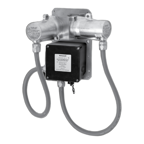
MAN0889_Issue 3_03/13 Searchline Excel Cross-Duct Technical Handbook 2. Overview 2.1 Introduction Searchline Excel Cross-Duct gas detector consists of a Transmitter and Receiver unit, and a Heated Reflector Panel. The Transmitter and Receiver unit generates and detects the infrared beam. The Heated Reflector Panel is mounted at the opposite side of the duct to reflect the beam from the Transmitter back to the Receiver. Note: THE INFRARED BEAM IS INVISIBLE AND EYE SAFE. Heated Reflector Panel Mounting Plate Mounting Block Transmitter Conduit Receiver Junction Box (type DVC100 (M) MK2) There are two ranges of Searchline Excel Cross-Duct gas detector. These are:... -
Page 10: Transmitter And Receiver Unit
MAN0889_Issue 3_03/13 Searchline Excel Cross-Duct Technical Handbook 2. Overview 2.2 Transmitter and Receiver Unit Slot for test filter Air Shield Gas In/Out Receiver Gassing Cell Beamsplitter Mounting Block Transmitter 2.2.1 Transmitter The Transmitter produces an intense, collimated infrared beam from a Xenon arc flashlamp. The Transmitter window is heated to minimise condensation and frosting. During particularly cold operating conditions, the heating of the Transmitter window is increased to turbo levels. -
Page 11: Mounting Block
MAN0889_Issue 3_03/13 Searchline Excel Cross-Duct Technical Handbook 2. Overview 2.2.3 Mounting Block The Transmitter and Receiver are factory aligned and fixed to a mounting block. They should not be disassembled. The mounting block has a top cover which can be removed to clean the Transmitter and Receiver windows. Inside the mounting block there is an angled window (the beamsplitter) which reflects the... -
Page 12: Installation And Operation
If you have any queries concerning your installation design, contact Honeywell Analytics or your local agents. Honeywell Analytics is committed to ensuring that customers achieve reliable operation of their Searchline Excel Cross-Duct Gas Detectors. For this reason, Searchline Excel Cross-Duct should only be installed by fully trained personnel (trained by Honeywell Analytics or a Honeywell Analytics authorised trainer). This training will provide the installer with a clear understanding of the Searchline Excel Cross-Duct product and the associated accessories and tools. -
Page 13: Location To Maximise Reliability And Availability
Since the Transmitter and Receiver protrude from the duct wall, adequate precautions should be taken to protect personnel. Intense Electromagnetic Fields - Searchline Excel Cross-Duct complies with EN50270 and as such is well protected from interference by electromagnetic fields. However, locations in close proximity to radio/radar transmitters, heavy electrical plant and high voltage power cables may experience field strengths in excess of those specified in the standard. Where possible, such locations should be avoided or units should be installed... -
Page 14: Orientation
3.3 Electrical Connections 3.3.1 General Searchline Excel Cross-Duct complies with the EN50270. In order to maintain compliance with these standards it is essential that the electrical installation of Excel is engineered correctly. Electrical installation standards vary for different countries, companies and applications and it is the responsibility of the installation design authority to determine the applicable standards and ensure compliance with them. -
Page 15: Transmitter And Receiver Connections Via Dvc100 (M) Mk2
The field cabling conductors should have sufficient cross sectional area to ensure that the minimum supply voltage applied to the gas detector is 18V. Searchline Excel Cross-Duct Receivers should not be installed in close proximity to the antennae of high powered radio, radar and satellite communication equipment. 3.3.2 Transmitter and Receiver Connections via DVC100 (M) MK2 3.3.3 Transmitter and Receiver Connections via DX100 (M) -
Page 16: Transmitter And Receiver Connections
MAN0889_Issue 3_03/13 Searchline Excel Cross-Duct Technical Handbook 3. Installation and Operation Control Cabinet DX100 (M) Junction Box Cross-Duct Reciever Connections Connections Cable Shield Modbus A Modbus B Screen Modbus Drain Instrument (clean) Earth Blue (B) Orange (A) Red (+24VDC) +24VDC - in... -
Page 17: Remote Installations
3.4.1 General The Searchline Excel Cross-Duct gas detector is designed to be operated from a nominal 24V DC supply. The supply voltage at the terminals must be within the range 18 to 32V for the Transmitter and Receiver unit, and within the range 18 to 28V for the Heated Reflector Panel. - Page 18 MAN0889_Issue 3_03/13 Searchline Excel Cross-Duct Technical Handbook 3. Installation and Operation Short Range Heated Reflector Panel (Part numbers 2104B0715, 2104B0717) Customer Connection Customer Connection Heater Resistance Terminal Identification Wire Colour (>20V) (<20V) White Black or Brown >20Vdc 100Ω Blue 18-20Vdc 68Ω Green Earth Earth Long Range Heated Reflector Panel (Part number 2104B0716) Customer Customer Terminal Identification...
-
Page 19: Power Supply Connections - Turbo Heating Disabled
MAN0889_Issue 3_03/13 Searchline Excel Cross-Duct Technical Handbook 3. Installation and Operation 3.4.2 Power Supply Connections - Turbo heating Disabled When connected as shown in section 3.3 Transmitter and Receiver Connections the Transmitter has turbo heating mode enabled. This means that during conditions of low ambient temperature, additional heating power is applied to the unit’s window to minimise condensation, frosting and snow buildup. -
Page 20: Installation Procedure
3.5 Installation Procedure 3.5.1 General Installing the Searchline Excel Cross-Duct is done in two stages. First the duct is prepared, and the Excel components mechanically fixed in place. Secondly, the electrical wiring is connected. The Transmitter and Receiver assembly must be fully assembled and mounted to the duct structure before making the electrical connections. -
Page 21: Heated Reflector Panel
MAN0889_Issue 3_03/13 Searchline Excel Cross-Duct Technical Handbook 3. Installation and Operation (1) Stick the supplied self-adhesive mounting plate cut-out template onto the duct wall in the position chosen for the Transmitter and Receiver unit. Note: The intersection of the bold lines on the template (point X) corresponds with the centre of the unit’s infrared beam. -
Page 22: Electrical Installation
• Power up the gas detector and set the interrogator for operation with Excel • Set the Excel real time clock • Initialise the Excel gas detector • Functional check with test filters • Finish 3.6.2 Connecting the Interrogator Connect the SHC1 Handheld Interrogator to the gas detector in one of the following ways: • v ia a Honeywell Analytics DVC100 (M)/ DX100 (M) Junction Box - connect the Interrogator directly to the junction box via the IS socket, e.g. Calibrator Type SHC1... - Page 23 MAN0889_Issue 3_03/13 Searchline Excel Cross-Duct Technical Handbook 3. Installation and Operation • via another type of junction box, e.g. Hawke PL612 - using the SHC Protection Device. See the following diagram and description and Appendix C - Spare Parts IS Connector Flying Lead Notes: The protection device must always be used for this type of connection.
-
Page 24: Power Up
MAN0889_Issue 3_03/13 Searchline Excel Cross-Duct Technical Handbook 3. Installation and Operation 3.6.3 Power Up (1) Apply power to the Searchline Excel Cross-Duct Transmitter and Receiver and Heated Reflector Panel units. (2) Press and hold the (Enter) key on the Interrogator keypad for at least two seconds. This switches on the unit. Note: Full details of the SHC1 Handheld Interrogator can be found in Calibrator Appendix A. -
Page 25: Setting The Real-Time Clock
MAN0889_Issue 3_03/13 Searchline Excel Cross-Duct Technical Handbook 3. Installation and Operation 3.6.4 Setting the Real-Time Clock The gas detector clock needs to be initially set so that faults, events, etc., can be accurately recorded and tracked for diagnostic purposes. (1) Select Calibrate from the Main menu by pressing the ▲ (up) and ▼ (down) keys on the keypad to navigate through the menu options. -
Page 26: Initialising The Searchline Excel Cross-Duct Gas Detector
Searchline Excel Cross-Duct Technical Handbook 3. Installation and Operation 3.6.5 Initialising the Searchline Excel Cross-Duct Gas Detector In this part of the procedure details about the gas detector must be entered so that the Interrogator can then complete the commissioning of the gas detector using the correct data. - Page 27 MAN0889_Issue 3_03/13 Searchline Excel Cross-Duct Technical Handbook 3. Installation and Operation (10) Press on the keypad and the display shows: Signals OK Ensure Zero gas then press Enter (11) Press and the display will show the following message whilst the unit is initialising: Zero Cal OK When the gas detector has completed initialisation, the following message is displayed for...
-
Page 28: Functional Check
The procedure for testing a Searchline Excel Cross-Duct using the functional test filters is as follows:- (1) Select DISPLAY from the Calibrate menu. (This inhibits the Searchline Excel Cross-Duct output). (2) Remove the top cover from the mounting block. The cover is retained by 3 x M4 captive bolts, and a chain attaches the lid to the mounting block when opened. -
Page 29: System Controller Calibration
3. Installation and Operation 3.7 System Controller Calibration This procedure is used to set up the system controller using the Searchline Excel Cross-Duct gas detector. A chosen fixed output signal is sent from the gas detector to the system controller allowing calibration of the 0 - 100% scale of the controller without having to use gas. The steps use procedures described in the previous section. -
Page 30: Installation Checks/ Tests
Searchline Excel Cross-Duct Technical Handbook 3. Installation and Operation (12) Turn off the Interrogator and disconnect it from the gas detector. Note: The recommended alarm level settings for Searchline Excel Cross-Duct are as follows:- Operating range Minimum low alarm Maximum high alarm 0.5m - 2.0m... - Page 31 MAN0889_Issue 3_03/13 Searchline Excel Cross-Duct Technical Handbook 3. Installation and Operation Searchline Excel Cross-Duct: Installation Check Sheet CUSTOMER/OPERATOR SITE / FACILITY SYSTEM TYPE: Short Range Long Range OPERATING RANGE GAS TABLE: METHANE DETECTOR LOCATION: TAG NO. (TX/RX): TAG NO. (Reflector): SER NO. (TX/RX): SER NO. (Reflector): MOD STATE MOD STATE (TX/RX): CERTIFICATION: (Reflector)
- Page 32 MAN0889_Issue 3_03/13 Searchline Excel Cross-Duct Technical Handbook 3. Installation and Operation The following notes are to help the installer enter the correct information onto the check sheet. Site/Facility Enter the name and geographical location of the site/facility. Operating Range Enter the distance (preferably in metres), between the Transmitter and Receiver unit and the Heated Reflector Panel.
- Page 33 MAN0889_Issue 3_03/13 Searchline Excel Cross-Duct Technical Handbook 3. Installation and Operation Supply Voltage Check that the supply voltage applied to the unit is within the specified 18V to 32V range (Transmitter and Receiver) or 18 to 28V range (Heated Reflector Panel) and is stable. Enter the supply voltage and stability, e.g. 22.5V, stable, 19V, +2V fluctuation Earthing Inspect the earth connections to the units. If the unit is connected to local metalwork or the safety/general use earth, enter ‘Local Safety. If the unit has been isolated from local metalwork/ earths and is connected to a clean, instrument earth, enter Instrument earth.
- Page 34 MAN0889_Issue 3_03/13 Searchline Excel Cross-Duct Technical Handbook 3. Installation and Operation Fault/Warning Log Check the fault/warning log. In order for the unit to complete installation satisfactorily, the ACTIVE FAULTS log must be CLEAR. Use the Handheld Interrogator to diagnose and remedy all ACTIVE FAULT. Wherever possible, it is recommended to CLEAR any ACTIVE WARNINGS, since these may lead to faults in the future.
-
Page 35: Maintenance
The gas detector should remain powered during these procedures. Caution: Searchline Excel Cross-Duct does not contain any user serviceable parts. Do not open or disassemble the Transmitter and Receiver unit (other than as instructed), or the Heated Reflector Panel. The warranty of units which have been opened is invalidated. -
Page 36: Re-Zero
4.3.1 Functional Checking with Gassing Cell (Short Range versions only) Searchline Excel Cross-Duct incorporates a built in gassing cell for functional test purposes. In order to use the gassing cell, the mounting block lid must be in place, to maintain a gas tight seal. -
Page 37: Functional Checking With Test Filters
MAN0889_Issue 3_03/13 Searchline Excel Cross-Duct Technical Handbook 4. Maintenance To get the best accuracy when using the gassing cell: (1) Ensure that the gassing cell contains fresh air, and perform a zero calibration on the Excel (2) Apply the test gas and allow sufficient time to fully fill the gassing cell and check that the Searchline Excel Cross-Duct output stabilises. A flow rate of less than 0.5 litres per minute is advisable, to avoid pressurising the gassing cell. (3) For a methane calibrated unit tested with 100%v/v methane (UL version) or 88%v/v methane (ATEX, IECEx... -
Page 38: Problem Solving
An electrical multimeter is also useful when diagnosing electrical/wiring problems. Refer to the troubleshooting tables in this chapter for a list of problems, possible causes and actions. Caution: Searchline Excel Cross-Duct does not contain any user serviceable parts. Do not open or disassemble the Transmitter and Receiver unit, or the Heated Reflector Panel. The warranty of units which have been opened is invalidated. - Page 39 MAN0889_Issue 3_03/13 Searchline Excel Cross-Duct Technical Handbook 5. Problem Solving Unit has been inhibited by the Release output from INHIBIT state using SHC1 Interrogator. Interrogator 1) Wait for 1 minute. When power-up routine is completed satisfactorily the unit’s output should exit the INHIBIT state.
- Page 40 MAN0889_Issue 3_03/13 Searchline Excel Cross-Duct Technical Handbook 5. Problem Solving The beam path has become Check that the beam path is clear from Transmitter and Receiver obscured to the Reflector Panel. Remove any obstruction if present. 1) Check that the Transmitter is flashing. When viewed on the No signal or very axis, an orange flash can be seen coming from the Transmitter.
- Page 41 MAN0889_Issue 3_03/13 Searchline Excel Cross-Duct Technical Handbook 5. Problem Solving 1) When Ex certified equipment is operated outside its certified range, its type approval certification is invalidated along with Diagnostics Unit has been operated at a its warranty. Such equipment should be removed from service report in potentially explosive atmospheres.
-
Page 42: Specifications
Tolerance IP rating IP66 and 67 Response to other gases Searchline Excel Cross-Duct is a methane gas detector. It should only be used to detect gas mixtures where methane is the main constituent (>70%) and the balance is C hydrocarbons. -
Page 43: Certification
MAN0889_Issue 3_03/13 Searchline Excel Cross-Duct Technical Handbook 7. Certification 7.1 General The Searchline Excel Cross-Duct Transmitter and Receiver unit is certified to Ex d and has the following ATEX, IECEx and UL approvals for worldwide acceptance: ATEX, IECEx II 2 G Ex d IIC T5 (Tamb -40 to +65°C) Gb Ex d IIC T6 (Tamb -40 to +40°C) Certificate numbers: BAS98ATEX2165X IECEx BAS 09.0100X Class 1 Groups B, C, D Class 1 Zone 1 AEx d IIB + Hydrogen (Amb -40°C to +65°C) -
Page 44: Conduit Technical Characteristics (Atex, Iecex Version)
MAN0889_Issue 3_03/13 Searchline Excel Cross-Duct Technical Handbook 7. Certification 7.2 Conduit Technical Characteristics (ATEX, IECEx version) Ingress Protection IP66 and 67. Temperature Rating -40 to +105ºC. A helically wound galvanised steel core with cotton packing and enhanced oil Construction resistant PVC covering. Covering material displays good resistance to dilute acids, alkalis and hydrocarbon products. -
Page 45: Transmitter
MAN0889_Issue 3_03/13 Searchline Excel Cross-Duct Technical Handbook 7. Certification 7.3 Certification Labels ATEX, IECEx 7.3.1 Transmitter 7.3.2 Receiver... -
Page 46: Heated Reflector Panel
MAN0889_Issue 3_03/13 Searchline Excel Cross-Duct Technical Handbook 7. Certification 7.3.3 Heated Reflector Panel... -
Page 47: System Diagram
MAN0889_Issue 3_03/13 Searchline Excel Cross-Duct Technical Handbook 7. Certification 7.3.4 System Diagram... - Page 48 MAN0889_Issue 3_03/13 Searchline Excel Cross-Duct Technical Handbook 7. Certification 7.3.5 ATEX Special Conditions of Safe Use 7.3.5.1 Transmitter and Receiver The integral supply cables must be mechanically protected and terminated in a suitable terminal or junction facility. The cover fixing screws shall be grade 12.9 minimum. 7.3.5.2 Heated Reflector Panel The integral supply cables must be mechanically protected and terminated in a suitable terminal or junction facility.
-
Page 49: Certification Labels Ul
MAN0889_Issue 3_03/13 Searchline Excel Cross-Duct Technical Handbook 7. Certification 7.4 Certification labels UL 7.4.1 Transmitter 7.4.2 Receiver... -
Page 50: Heated Reflector Panel
MAN0889_Issue 3_03/13 Searchline Excel Cross-Duct Technical Handbook 7. Certification 7.4.3 Heated Reflector Panel... -
Page 51: System Diagram With Dx100M Termination Unit
MAN0889_Issue 3_03/13 Searchline Excel Cross-Duct Technical Handbook 7. Certification 7.4.4 System Diagram With DX100(M) Termination Unit... -
Page 52: Warranty Summary
MAN0889_Issue 3_03/13 Searchline Excel Cross-Duct Technical Handbook 8. Warranty Summary Honeywell Analytics warrants the Searchline Excel Cross-Duct against defective parts and workmanship and will repair or (at its option) replace any instruments which are or may become defective under proper use within 36 months from date of shipment from Honeywell Analytics. This warranty does not cover consumable items, normal wear and tear or damage caused by accident, abuse, improper installation, poisons, contaminants or abnormal operating conditions. -
Page 53: Appendix A - Handheld Interrogator
MAN0889_Issue 3_03/13 Searchline Excel Cross-Duct Technical Handbook Appendix A - Handheld Interrogator A.1 Introduction This appendix provides reference information about the SHC1 Handheld Interrogator. The interrogator provides the user end of a two-way communication link between the Excel system and the operator. It features facilities which let the operator configure, align, functionally test and diagnose faults in the system. The appendix gives: • an overview of the interrogator features •... -
Page 54: Connection To System
If the ▲ and ▼ keys are used to advance beyond the end of a list a wrap around to the other end of the list occurs. A.3 Connection to System Details of how to connect the interrogator to the Searchline Excel Cross-Duct are given in Chapter 3. The diagram shows a typical example. Calibrator... -
Page 55: Basic User Tasks
MAN0889_Issue 3_03/13 Searchline Excel Cross-Duct Technical Handbook Appendix A - Handheld Interrogator A.4 Basic User Tasks Switching On (1) Press for two seconds. The unit recalls its previously set operating mode, i.e. EXCEL, OPTIMA or OPTIMA PLUS, and displays the following message for approximately three seconds:... -
Page 56: Menus
MAN0889_Issue 3_03/13 Searchline Excel Cross-Duct Technical Handbook Appendix A - Handheld Interrogator A.5 Menus The interrogator top level menu structure and menu choices are as follows. All menu options are implemented by pressing the keypad key. The menu options and types are shown in the... -
Page 57: Main Menu
MAN0889_Issue 3_03/13 Searchline Excel Cross-Duct Technical Handbook Appendix A - Handheld Interrogator A.5.1 Main Menu This menu consists of the following sub menu options: Display Display gas and other unit readings. Calibrate I nstall and calibrate the system, force the analogue output, show the calibration coefficients or show the instrument status. Diagnose Inspect the fault and warning logs, perform a self-test or perform a soft reset. -
Page 58: Calibrate Menu
MAN0889_Issue 3_03/13 Searchline Excel Cross-Duct Technical Handbook Appendix A - Handheld Interrogator Signal Magnitude Show the level of the sample and reference signals.The display is in the following format: Sample: aaaaaaa Ref: bbbbbbb aaaaaaa where: Signal magnitude for the sample channel. bbbbbbb Signal magnitude for the reference channel. Dynamic Reserve Shows the acceptable drop in signal level before beam block occurs as a percentage of the current signal level. The display is in the following format:... - Page 59 MAN0889_Issue 3_03/13 Searchline Excel Cross-Duct Technical Handbook Appendix A - Handheld Interrogator Before the selected sub menu operation is started the following message is displayed for at least three seconds: Inhibiting 4-20 Please Wait The analogue output is inhibited and the chosen sub menu operation proceeds. After the sub menu operation...
- Page 60 This starts the system self test process. The following message is displayed: Self Test Please Wait When finished the interrogator displays the following message for at least three seconds: Checks Passed The following message is now displayed: SIG: TGT: Alignment No alignment adjustments are provided for the Searchline Excel Cross-Duct. If the mechanical installation is satisfactory Searchline Excel Cross-Duct can now be initialised. Press Enter on the keypad and the display shows: Signals OK...
- Page 61 MAN0889_Issue 3_03/13 Searchline Excel Cross-Duct Technical Handbook Appendix A - Handheld Interrogator Ensure Zero Gas then press Enter Press Enter and the display will show the following message: Zero Cal OK This message is displayed for three seconds at the end of a successful initialisation process. Installation complete Note: The Searchline Excel system is live after a successful initialisation.
- Page 62 MAN0889_Issue 3_03/13 Searchline Excel Cross-Duct Technical Handbook Appendix A - Handheld Interrogator where: Day. Month. Last two digits of the year. Note: The time and date will not be updated unless both are entered and accepted without error. Cal Sensor This menu option zeros the system.
-
Page 63: Diagnose Menu
MAN0889_Issue 3_03/13 Searchline Excel Cross-Duct Technical Handbook Appendix A - Handheld Interrogator Normal mA This menu option returns the system to its normal analogue output state, irrespective of its previous state. If successful, the following message is displayed for three seconds: 4-20mA Released Show Status This menu option displays the calibration and configuration status of the system. The status information is displayed in the following format: ccccccccccccccc where: cccccccc... Title of the calibration status field. - Page 64 MAN0889_Issue 3_03/13 Searchline Excel Cross-Duct Technical Handbook Appendix A - Handheld Interrogator If there are one or more faults present, then the faults are displayed one at a time. Use the ▲ and ▼ keys to navigate the list. If no active faults are present the display shows the following for three seconds: None Present The Diagnose sub menu is then displayed.
-
Page 65: Config Menu
MAN0889_Issue 3_03/13 Searchline Excel Cross-Duct Technical Handbook Appendix A - Handheld Interrogator Overrange ERR_EXCEL_OVERRANGE An overrange signal has occurred. Power Failed ERR EXCEL_LOG_POWER_FAIL The gas detector has suffered an internal power failure. Reset Occurred ERR_EXCEL_RESET A gas detector reset has occurred. - Page 66 MAN0889_Issue 3_03/13 Searchline Excel Cross-Duct Technical Handbook Appendix A - Handheld Interrogator ccccccc... where: Title of the configuration setting. vvvvvvvv Setting value. Note: The settings are not field configurable: Gas Configuration Display Text Max Value Step Size Min Value Parameters 1 = Methane Gas ID...
-
Page 67: Chg Mode
MAN0889_Issue 3_03/13 Searchline Excel Cross-Duct Technical Handbook Appendix A - Handheld Interrogator A.5.6 Chg Mode This menu option toggles the operating mode of the interrogator between Excel, Optima and Optima Plus to match the gas detector it is attached to. When invoked the mode is displayed in the identification banner (the same as the one displayed when the unit is switched on) for three seconds as follows: Z - SHC1 aaaaaa Interrogator 4V0... -
Page 68: Appendix B - Glossary
MAN0889_Issue 3_03/13 Searchline Excel Cross-Duct Technical Handbook Appendix B - Glossary B.1 Terminology Ex d Flame proof or explosion proof within the confines of the European series of standards EN60079. An enclosure that can withstand the pressure developed during the internal explosion of an explosive mixture and that prevents transmission of the explosion to the explosive atmosphere surrounding the enclosure. -
Page 69: Open Path Detector Measurement Units
Calibrator Type SHC1 The Searchline Excel Cross-Duct operates with a very short path length, making it reasonable to assume that the gas concentration is uniform across the duct. Therefore Searchline Excel Cross-Duct uses the duct width to convert the measured gas reading from LEL.m to %LEL. It is important that the duct width is entered correctly during commissioning otherwise the detector could report a significant under or over read of gas concentration. -
Page 70: Appendix C - Accessories & Spare Parts
MAN0889_Issue 3_03/13 Searchline Excel Cross-Duct Technical Handbook Appendix C - Accessories & Spare Parts C.1 System Units The following table lists the different types of system units and provides the part numbers for the various certification options. All types of Transmitters and Receivers include conduit and glands. - Page 71 Searchline Excel Cross-Duct Technical Handbook Appendix C - Accessories & Spare Parts Gas Test Equipment 2104N3000 Searchline Excel Cross-Duct Test filters kit & Manual 2108D0271 Remote Gassing Pipe Manuals (Hard Copy) Note: Electronic copies of the manuals are supplied on CD with each instrument...
- Page 72 Thank you for reading this data sheet. For pricing or for further information, please contact us at our UK Office, using the details below. UK Office Keison Products, P.O. Box 2124, Chelmsford, Essex, CM1 3UP, England. Tel: +44 (0)330 088 0560 Fax: +44 (0)1245 808399 Email: sales@keison.co.uk...
Need help?
Do you have a question about the Searchline Excel Cross-Duct and is the answer not in the manual?
Questions and answers