
Subscribe to Our Youtube Channel
Related Manuals for Kramer VS-88DTP


Summary of Contents for Kramer VS-88DTP
- Page 1 K R A ME R E LE CT R O N IC S L T D . USER MANUAL MODEL: VS-88DTP 8x8 DVI - Twisted Pair Matrix Switcher P/N: 2900-000749 Rev 2...
-
Page 3: Table Of Contents
Getting Started Achieving the Best Performance Safety Instructions Recycling Kramer Products Overview Defining the VS-88DTP 8x8 DVI - Twisted Pair Matrix Switcher Using the IR Transmitter Installing the VS-88DTP in a Rack Connecting the VS-88DTP Connecting to the VS-88DTP via RS-232... - Page 4 Figures Figure 1: VS-88DTP 8x8 DVI - Twisted Pair Matrix Switcher Front Panel Figure 2: VS-88DTP 8x8 DVI - Twisted Pair Matrix Switcher Rear Panel Figure 3: Connecting the VS-88DTP 8x8 DVI - Twisted Pair Matrix Switcher Figure 4: RS-485 DIP-switches...
-
Page 5: Introduction
Scan Converters and Scalers; GROUP 8: Cables and Connectors; GROUP 9: Room Connectivity; GROUP 10: Accessories and Rack Adapters and GROUP 11: Sierra Products. Congratulations on purchasing your Kramer VS-88DTP 8x8 DVI - Twisted Pair Matrix Switcher, which is ideal for the following typical applications: •... -
Page 6: Getting Started
Do not secure the cables in tight bundles or roll the slack into tight coils • Avoid interference from neighboring electrical appliances that may adversely influence signal quality • Position your Kramer VS-88DTP away from moisture, excessive sunlight and dust Safety Instructions Caution: There are no operator-serviceable parts inside the unit... -
Page 7: Recycling Kramer Products
Kramer Electronics has made arrangements with the European Advanced Recycling Network (EARN) and will cover any costs of treatment, recycling and recovery of waste Kramer Electronics branded equipment on arrival at the EARN facility. For details of Kramer’s recycling arrangements in your particular country go to our recycling pages at http://www.kramerelectronics.com/support/recycling/. -
Page 8: Overview
• HDTV compatibility (no HDCP compliance) • DGKat™ Signal Integration that converts TMDS as well as control and communication to signals that run over twisted pair cables. Kramer strongly recommends using Kramer DGKat™ cables designed specifically for optimum performance •... -
Page 9: Defining The Vs-88Dtp 8X8 Dvi - Twisted Pair Matrix Switcher
Kramer's BC-DGKat524, BC-DGKat623 or BC-DGKat7a23 cables. The transmission range depends on the signal resolution, graphics card and display used. The distance using non-Kramer CAT 5, CAT 6, and CAT 7 cables may not reach these ranges. Use only shielded cable where both ends of the shield are soldered to ground. -
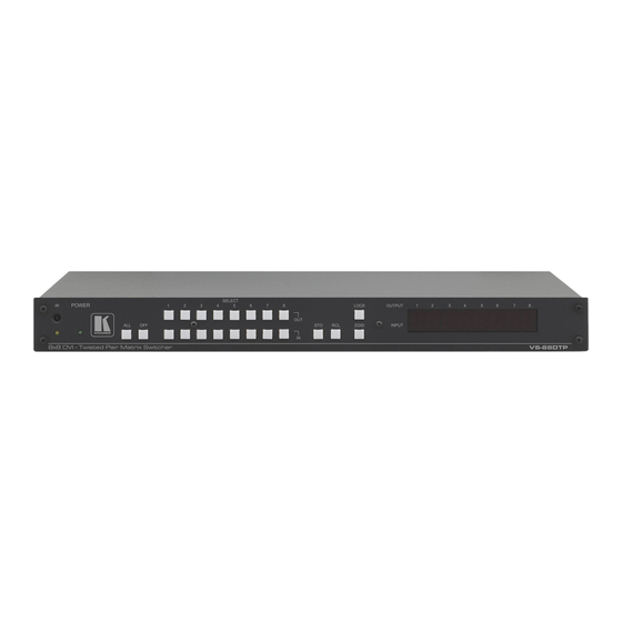
Page 10: Figure 1: Vs-88Dtp 8X8 Dvi - Twisted Pair Matrix Switcher Front Panel
Figure 1: VS-88DTP 8x8 DVI - Twisted Pair Matrix Switcher Front Panel Feature Function IR LED Lights yellow when receiving a signal from an IR remote control IR Sensor IR remote control signal receiver POWER LED Lights green when the device is powered on... -
Page 11: Figure 2: Vs-88Dtp 8X8 Dvi - Twisted Pair Matrix Switcher Rear Panel
5.2.2 ) Up = Off, Down = On. Default = On DIP-switch 2 Sets the Programming mode. Only for the use of Kramer service personnel. Default = Off RS-485 3-pin Terminal Block Connect to a serial controller or to another VS-88DTP unit. -
Page 12: Using The Ir Transmitter
This distance can be extended to up to 60 meters when used with three extension cables (Model: C-A35M/A35F-50). Before using the external IR receiver, be sure to arrange for your Kramer dealer to insert the internal IR connection cable (P/N: 505-70434010-S) with the 3.5mm connector that fits into the REMOTE IR opening on the rear panel. -
Page 13: Installing The Vs-88Dtp In A Rack
Installing the VS-88DTP in a Rack This section provides instructions for rack mounting the unit. VS-88DTP - Installing the VS-88DTP in a Rack... -
Page 14: Connecting The Vs-88Dtp
VS-88DTP. After connecting your VS-88DTP, connect its power and then switch on the power to each device. To connect the VS-88DTP as illustrated in the example in Figure 1. Connect up to eight DVI sources (for example, computer graphics sources) to the IN 1 to IN 8 DVI connectors. -
Page 15: Connecting To The Vs-88Dtp Via Rs-232
Figure 3: Connecting the VS-88DTP 8x8 DVI - Twisted Pair Matrix Switcher Connecting to the VS-88DTP via RS-232 You can connect to the VS-88DTP via an RS-232 connection using, for example, a PC. Note that a null-modem adapter/connection is not required. -
Page 16: Connecting A Pc Or Controller To The Rs-485 Port
Connecting a PC or Controller to the RS-485 Port You can operate the VS-88DTP via the RS-485 port from a distance of up to 1200m (3900ft) using any device equipped with an RS-485 port (for example, a PC). For successful communication, you must set the RS-485 machine number and bus termination. -
Page 17: Figure 4: Rs-485 Dip-Switches
5.2.2 Setting the RS-485 Bus Termination DIP-switch 1 sets the RS-485 bus termination of the VS-88DTP. Only the first and last physical units on the RS-485 bus must be terminated, all others must be unterminated. Moving the DIP-switch up turns the termination off (default), moving the switch down enables the termination. -
Page 18: Figure 5: Rs-485 Termination Dip-Switch
Figure 5: RS-485 Termination DIP-switch 5.2.3 Connecting and Controlling Multiple VS-88DTP Devices You can daisy-chain up to 16 VS-88DTP devices with operation via RS-232 from a PC or serial controller (see Figure To daisy-chain up to 16 VS-88DTP devices: 1. Connect the RS-232-1 port on the first VS-88DTP device to the PC (see Section Alternatively, the RS-485 port could be used for PC control. -
Page 19: Connecting The Vs-88Dtp Via Ethernet
5.3.1 Connecting to the Ethernet Port Directly to a PC You can connect the Ethernet port of the VS-88DTP to the Ethernet port on your PC, via a crossover cable with RJ-45 connectors. This type of connection is recommended for identifying the... -
Page 20: Figure 7: Local Area Connection Properties Window
5. Select the Internet Protocol (TCP/IP) and click the Properties Button (see Figure Figure 7: Local Area Connection Properties Window 6. Select Use the following IP Address, and fill in the details as shown in Figure 7. Click OK. Figure 8: Internet Protocol (TCP/IP) Properties Window VS-88DTP - Connecting the VS-88DTP... - Page 21 5.3.2 Connecting to the Ethernet Port via a Network Hub You can connect the Ethernet port of the VS-88DTP to the Ethernet port on a network hub or network router, via a straight through cable with RJ-45 connectors. VS-88DTP - Connecting the VS-88DTP...
-
Page 22: Operating The Vs-88Dtp
To disconnect one output: 1. Press the required OUT button 2. Press OFF. The selected output is disconnected. To disconnect all outputs at once: 1. Press the ALL button. 2. Press OFF. All outputs are disconnected. VS-88DTP - Operating the VS-88DTP... -
Page 23: Storing And Recalling Setups In Presets
The device switches to Protocol 2000 and the display shows 2000 To switch to Protocol 3000: • Press the Output 1 and Output 3 buttons at the same time. The device switches to Protocol 3000 and the display shows 3000 VS-88DTP - Operating the VS-88DTP... -
Page 24: Acquiring The Edid
2. Press the EDID button. The EDID buttons flashes. 3. Press the SELECT IN button to which the first EDID will be copied (for example, IN 1). The selected input number flashes on the display. VS-88DTP - Operating the VS-88DTP... -
Page 25: Acquiring The Default Edid
The selected input number flashes on the display. 3. Press the OFF button until a “0” (zero) appears on the display. 4. Press the EDID button. The process is complete when the display returns to normal. VS-88DTP - Operating the VS-88DTP... -
Page 26: Locking And Unlocking The Front Panel Buttons
To control several units via the Ethernet, connect the Master unit (Machine # 1) via the Ethernet port to the LAN port of your PC. Use your PC initially to configure the settings (see Section 5.3). VS-88DTP - Operating the VS-88DTP... -
Page 27: Controlling The Vs-88Dtp Remotely Via Ethernet
• Enable Javascript in your browser Connecting to the VS-88DTP via your Browser Make sure that your PC is connected via a network to the VS-88DTP and do the following: 1. Open your Internet browser. VS-88DTP - Controlling the VS-88DTP Remotely via Ethernet... -
Page 28: Figure 11: Entering The Ip Number In The Address Bar
Figure 11: Entering the IP Number in the Address Bar The Loading page appears. Figure 12: The Loading Page The first time you run the Kramer applet the following security warning appears: VS-88DTP - Controlling the VS-88DTP Remotely via Ethernet... -
Page 29: Figure 13: First Time Security Warning
There are two remote operation Web pages: • Main switching matrix (see Section • Configuration (see Section Select a page by clicking on the relevant link on the left hand side of the window. VS-88DTP - Controlling the VS-88DTP Remotely via Ethernet... -
Page 30: The Main Switching Matrix Page
Switching an Input to an Output To switch an input to an output, for example, input 1 to output 4: 1. Click the required point within the switching matrix grid (In 1, Out 4). VS-88DTP - Controlling the VS-88DTP Remotely via Ethernet... -
Page 31: Figure 15: Selecting A Switching Point On The Matrix
The button outline becomes dark. 2. Click the required point in the switching matrix grid (In 1, Out 5). The switching icon outline appears, and the Take and Cancel buttons change from gray to dark blue. VS-88DTP - Controlling the VS-88DTP Remotely via Ethernet... -
Page 32: Figure 16: Switching In The Offline Mode
Presets that contain a configuration are displayed with a blue background; presets with no configuration have a white background. When you select a preset, the Store button changes from gray to dark blue. VS-88DTP - Controlling the VS-88DTP Remotely via Ethernet... -
Page 33: Figure 17: Selecting Preset 07
Presets that contain a configuration are displayed with a blue background; presets with no configuration have a white background. When you select a preset that contains a configuration, the Recall button changes from gray to dark blue. VS-88DTP - Controlling the VS-88DTP Remotely via Ethernet... -
Page 34: Figure 18: Selecting Preset 03
Note: You can also recall a preset in the Offline mode (see Figure 19) and make it active when you press the Take button (see Section 7.2.2 Figure 19: Recalling a Preset in Offline Mode VS-88DTP - Controlling the VS-88DTP Remotely via Ethernet... -
Page 35: The Configuration Page
The Configuration page lets you edit the IP-related settings and only view the others. Editable fields have a white background. Figure 20: Configuration Page The following IP-related settings can be edited: • Machine name • Fixed IP Address/DHCP • Gateway • Subnet Mask VS-88DTP - Controlling the VS-88DTP Remotely via Ethernet... - Page 36 A message appears showing that the settings have been successfully changed. 4. If the IP address was changed or you selected DHCP, reload the Web page using the new name or IP address. VS-88DTP - Controlling the VS-88DTP Remotely via Ethernet...
-
Page 37: Technical Specifications
10% to 90%, RHL non-condensing DIMENSIONS: 19" x 7" x 1U (W, D, H) WEIGHT: 2.5kg (5.5lbs) approx. ACCESSORIES: Power cord, IR transmitter, rack “ears” OPTIONS: External remote IR receiver cable Specifications are subject to change without notice at http://www.kramerelectronics.com VS-88DTP - Technical Specifications... -
Page 38: Default Communication Parameters
The Windows®-based Kramer control software (available for download the latest software from our Web site at http://www.kramerelectronics.com) operates with protocol 2000. If the VS-88DTP is set to protocol 3000, it is automatically switched to protocol 2000 VS-88DTP - Default Communication Parameters... -
Page 39: Default Edid
Default EDID Each input on the VS-88DTP is loaded with a factory default EDID. Monitor: Model name VS-88DTP Manufacturer Plug and Play ID KRM0200 Serial number Manufacture date 2006, ISO week 12 ------------------------- EDID revision Input signal type Digital (DVI) - Page 40 Report Information: Date generated 21-Jun-11 Software revision 2.53.0.861 Data source File Operating system 5.1.2600.2.Service Pack 3 Raw Data: 00,FF,FF,FF,FF,FF,FF,00,2E,4D,00,02,01,00,00,00,0C,10,01,03,81,46,27,78,0A,D5,7C,A3,57,49,9C,25, 11,48,4B,FF,FF,80,8B,C0,81,00,95,00,81,40,81,80,90,40,B3,00,A9,40,0E,1F,00,80,51,00,1E,30,40,80, 37,00,6F,13,11,00,00,1E,28,3C,80,A0,70,B0,23,40,30,20,36,00,06,44,21,00,00,1A,00,00,00,FC,00,56, 53,2D,38,38,44,54,50,0A,20,20,20,20,00,00,00,FD,00,56,53,2D,38,38,44,54,50,0A,20,20,20,20,00,83 VS-88DTP - Default EDID...
-
Page 41: Updating The Vs-88Dtp Firmware
Updating the VS-88DTP Firmware Instructions for upgrading the VS-88DTP firmware can be found at http://www.kramerelectronics.com. VS-88DTP - Updating the VS-88DTP Firmware... -
Page 42: Table Of Ascii Codes For Serial Communication (Protocol 3000)
Table of ASCII Codes for Serial Communication (Protocol 3000) The following table lists the ASCII video signal codes that switch an input to an output for a single VS-88DTP machine in Protocol 3000. For more detailed information, see Section 14.2 OUT 1... -
Page 43: Hex Codes For Serial Communication (Protocol 2000)
The Hex codes listed in this section are used to set video channels for a single machine (set as Machine 1) connected via either RS-232 or Ethernet. Similar hex codes are used when the VS-88DTP is connected via RS-485 and the machine is set to number 2. -
Page 44: Kramer Protocol
Kramer Protocol By default, the VS-88DTP is set to protocol 3000 (see Section 14.2) but is also compatible with Kramer’s Protocol 2000 (see Section 14.3 You can download our user-friendly “Software for Calculating Hex Codes for Protocol 2000” from the technical support section on our Web site at: http://www.kramerelectronics.com... -
Page 45: Command String
Note: A string can contain more than one command. Commands are separated by a pipe ( '|' ) character. Message starting character '#' – For host command/query '~' – For machine response VS-88DTP - Kramer Protocol... -
Page 46: Entering Commands
You can directly enter all commands using a terminal with ASCII communications software, such as HyperTerminal, Hercules, etc. Connect the terminal to the serial, Ethernet, or USB port on the Kramer device. To enter CR , press the Enter key. ( LF is also sent but is ignored by command parser). -
Page 47: Maximum String Length
AV IN>OUT, IN>OUT, …RESULT Short form: V IN>OUT, IN>OUT, … Note: When AFV mode is active, this command will switch also audio. If audio is breakaway – device display mode will change to show audio connections status. VS-88DTP - Kramer Protocol... - Page 48 Short form: PSTO PRESET Recall saved preset PRST-RCL PRESET PRST-RCL PRESET RESULT Short form: PRCL PRESET Read video connections PRST-VID? PRESET,OUT PRST-VID PRESET, IN>OUT from saved preset Short form: PVID? PRESET,OUT PRST-VID PRESET, IN>1, IN>2,… PRST-VID? PRESET, * VS-88DTP - Kramer Protocol...
- Page 49 Syntax Response Protocol Handshaking ~OK CRLF MODEL? Read device model MODEL MACHINE_MODEL Read device serial SN SERIAL_NUMBER number VERSION? Read device firmware VERSION MAJOR .MINOR .BUILD version .REVISION Set machine name NAME MACHINE_NAME NAME MACHINE_NAME RESULT VS-88DTP - Kramer Protocol...
- Page 50 ETHP? PROTOCOL = TCP / UDP (transport layer protocol) PORT ethernet port to enter protocol 3000 commands. 1-65535 = User defined port 0 - reset port to factory default (50000 for UDP, 5000 for TCP) VS-88DTP - Kramer Protocol...
-
Page 51: Kramer Protocol 2000
14.3 Kramer Protocol 2000 The Kramer Protocol 2000 RS-232/RS-485 communication uses four bytes of information as defined below. DESTINATION INSTRUCTION 1st byte INPUT 2nd byte OUTPUT 3rd byte MACHINE NUMBER 4th byte 1st BYTE: Bit 7 – Defined as 0. -
Page 52: Instruction Codes For Protocol 2000
OUTPUT is assigned the value of the requested parameter. The replies to instructions 10 and 11 are as per the definitions in instructions 7 and 8 respectively. For example, if the present status of machine number 5 is breakaway setting, then the reply to the HEX code would be HEX codes VS-88DTP - Kramer Protocol... - Page 53 (in real-time). For example, if input 3 is detected as invalid, the unit will send the HEX codes If input 7 is detected as valid, then the unit will send HEX codes VS-88DTP - Kramer Protocol...
- Page 55 For the latest information on our products and a list of Kramer distributors, visit our Web site where updates to this user manual may be found. We welcome your questions, comments, and feedback. Web site: www.kramerelectronics.com E-mail: info@kramerel.com SAFETY WARNING...
Need help?
Do you have a question about the VS-88DTP and is the answer not in the manual?
Questions and answers