
Related Manuals for Kramer VS-88A


Summary of Contents for Kramer VS-88A
- Page 1 Kramer Electronics, Ltd. USER MANUAL Models: VS-88A, VS-88V, SD-7588A, SD-7588V, RC-8000 88 Series...
-
Page 2: Table Of Contents
Overview The 88 Series High Quality Performance Recommendations Your Matrix Switchers Your VS-88A 8x8 Balanced Audio Matrix Switcher Your VS-88V 8x8 Video Matrix Switcher Your SD-7588A 8x8 Digital Audio Matrix Switcher Your SD-7588V 8x8 SDI Matrix Switcher Your RC-8000 Remote Controller... - Page 3 Figure 8: System Connection: Switchers and the PC Figure 9: Component Switcher: VS-88V Group Connection Tables Table 1: VS-88A 8x8 Balanced Audio Matrix Switcher Features Table 2: VS-88V 8x8 Video Matrix Switcher Features Table 3: SD-7588A 8x8 Digital Audio Matrix Switcher Features...
-
Page 4: Introduction
GROUP 6: Accessories and Rack Adapters; GROUP 7: Scan Converters and Scalers; and GROUP 8: Cables and Connectors 2 Downloadable from our Web site at http://www.kramerelectronics.com 3 Download up-to-date Kramer user manuals from the Internet at this URL: http://www.kramerelectronics.com 4 The complete list of Kramer cables is on our Web site at http://www.kramerelectronics.com... -
Page 5: Overview
3.1 The 88 Series The 88 Series includes the following items: VS-88A (stereo audio matrix switcher for analog balanced audio) VS-88V (video matrix switcher for analog composite video) SD-7588A (audio matrix switcher for digital audio) -
Page 6: Your Matrix Switchers
Includes 15 preset memory locations for quickly and easily accessing the most frequently used configurations May be used with the RC-8000, an optional remote controller (see section 0) Functions as a standalone unit as well as part of a Kramer multi-signal switcher system Figure 1 and Table 1 define the VS-88A: 1 To install a switcher in a rack, see section 5 2 Switchers in the 88 Series share identical front panel controls. -
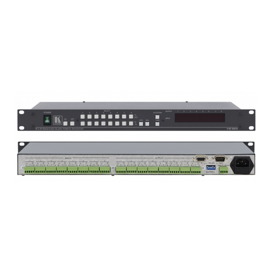
Page 7: Figure 1: Vs-88A 8X8 Balanced Audio Matrix Switcher
Your Matrix Switchers Figure 1: VS-88A 8x8 Balanced Audio Matrix Switcher KRAMER: SIMPLE CREATIVE TECHNOLOGY... -
Page 8: Table 1: Vs-88A 8X8 Balanced Audio Matrix Switcher Features
Your Matrix Switchers Table 1: VS-88A 8x8 Balanced Audio Matrix Switcher Features Feature Function POWER Switch Illuminated switch supplying power to the unit ALL Button Pressing ALL before pressing an INP button, connects that input to all outputs OFF Button Pressing OFF after pressing an OUT button disconnects that output from the inputs. -
Page 9: Your Vs-88V 8X8 Video Matrix Switcher
May be used with the RC-8000, an optional remote controller (see section 0) Functions as a standalone unit as well as part of a Kramer multi-signal switcher system Can be combined as part of a group of VS-88V switchers that comprise a... -
Page 10: Figure 2: Vs-88V 8X8 Video Matrix Switcher
Your Matrix Switchers Figure 2: VS-88V 8x8 Video Matrix Switcher... -
Page 11: Table 2: Vs-88V 8X8 Video Matrix Switcher Features
6 If the unit is not the first unit in the line, connects to the RS-232 OUT 9-PIN D SUB port of the previous unit in the line 7 The 88 Series RS-485 connector has 4 pins, and the Remote Controller RS-485 connector has just 3 pins 8 If the unit is the final unit in the daisy-chain connection, no termination is required KRAMER: SIMPLE CREATIVE TECHNOLOGY... -
Page 12: Your Sd-7588A 8X8 Digital Audio Matrix Switcher
Includes 15 preset memory locations for quickly and easily accessing the most frequently used configurations May be used with the RC-8000, an optional remote controller (see section 0) Functions as a standalone unit as well as part of a Kramer multi-signal switcher system Figure 3 and Table 3 define the SD-7588A: 1 Which includes digital and analog video, digital and analog audio and RS-422 control switchers. -
Page 13: Figure 3: Sd-7588A 8X8 Digital Audio Matrix Switcher
Your Matrix Switchers Figure 3: SD-7588A 8x8 Digital Audio Matrix Switcher KRAMER: SIMPLE CREATIVE TECHNOLOGY... -
Page 14: Table 3: Sd-7588A 8X8 Digital Audio Matrix Switcher Features
Your Matrix Switchers Table 3: SD-7588A 8x8 Digital Audio Matrix Switcher Features Feature Function Power Switch Illuminated switch supplying power to the unit ALL Button Pressing ALL before pressing an INPUT button, connects that input to all outputs (ALL= All Outputs) OFF Button Pressing OFF after pressing an OUTPUT button disconnects that output from the inputs. -
Page 15: Your Sd-7588V 8X8 Sdi Matrix Switcher
Includes 15 preset memory locations for quickly and easily accessing the most frequently used configurations May be used with the RC-8000, an optional remote controller (see section 0) Functions as a standalone unit as well as part of a Kramer multi-signal switcher system Figure 4 and Table 4 define the SD-7588V: 1 Which includes digital and analog video, digital and analog audio, and RS-422 control switchers. -
Page 16: Figure 4: Sd-7588V 8X8 Sdi Matrix Switcher
Your Matrix Switchers Figure 4: SD-7588V 8x8 SDI Matrix Switcher... -
Page 17: Table 4: Sd-7588V 8X8 Sdi Matrix Switcher Features
7 If the unit is not the first unit in the line, connects to the RS-232 OUT 9-pin D-sub port of the previous unit in the line 8 If the unit is the final unit in the daisy-chain connection, no termination is required KRAMER: SIMPLE CREATIVE TECHNOLOGY... -
Page 18: Your Rc-8000 Remote Controller
Your Matrix Switchers 4.5 Your RC-8000 Remote Controller The RC-8000 is an optional remote controller for accessing and controlling switchers in the 88 Series. In addition, the RC-8000: Supports the creation of any configuration that consists of a PC, an unlimited number of remote controllers, and up to any eight 88 Series switchers, activating all the functions of the connected devices, individually or grouped... -
Page 19: Figure 5: Rc-8000 Remote Controller
Your Matrix Switchers Rear Panel Sockets Power RS-485 +12v DC - + G Figure 5: RC-8000 Remote Controller KRAMER: SIMPLE CREATIVE TECHNOLOGY... -
Page 20: Table 5: Rc-8000 Remote Controller Top Panel Features
Your Matrix Switchers Table 5 and Table 6 define the features and functions of the RC-8000: Table 5: RC-8000 Remote Controller Top Panel Features Feature Function MACHINE IN Enable toggle between the standalone and the IN SYSTEM modes of any SYSTEM Buttons switcher, and viewing the status and control of the corresponding switcher (from... -
Page 21: Installing In A Rack
5. The machine is earthed (grounded) in a reliable way power and is connected only to an electricity socket with If you are using a Kramer rack grounding. Pay particular attention to situations where adapter kit (for a machine that is not electricity is supplied indirectly (when the power cord 19"), see the Rack Adapters user... -
Page 22: Connecting Your Matrix Switchers
Connecting Your Matrix Switchers Connecting Your Matrix Switchers This section describes how to: Set the dipswitches (refer to section 6.1) Connect a standalone unit (refer to section 6.2) Connect several units with/without the remote controller (refer to section 6.3) Connect several units and the PC (refer to section 6.4) Connect a component switcher (refer to section 6.5) 6.1 Dipswitch Settings Each 88 Series switcher includes a rear panel set of six dipswitches, as Figure... -
Page 23: Connecting A Standalone Unit
# 5 OFF and dipswitch # 6 ON Connect all the 4 terminals to the RS-485 interface connectors Operate the front panel controls of any switcher Figure 7 illustrates a typical system connection: KRAMER: SIMPLE CREATIVE TECHNOLOGY... -
Page 24: Figure 7: Rs-485 System Connection: Switchers And Remote Controllers
Connecting Your Matrix Switchers Figure 7: RS-485 System Connection: Switchers and Remote Controllers You can connect up to 24 remote controllers and up to 8 switchers per system. However, when connecting less than 8 switchers, you can connect more remote controllers 1 RS-485 connection supports up to 32 devices, that is, switchers and remote controllers. -
Page 25: Connecting Several Units And The Pc
RS-232 Figure 8: System Connection: Switchers and the PC 1 The 88 Series firmware complies with Kramer Protocol-2000 (version 3.1 and higher) 2 Make one-to-one connections (that is, uncrossed) 3 Often the PC has no RS-485 Com port and so both are required simultaneously... -
Page 26: Connecting A Component, Y/C, Rgbs Or Rgbhv Switcher
Connecting Your Matrix Switchers 6.5 Connecting a Component , Y/C, RGBS or RGBHV Switcher switcher consists of three VS-88V switchers, interconnected as A component one group, with one of the switchers set as the Master. A component switcher can function in the IN SYSTEM or standalone mode. Similarly, you can configure two VS-88V switchers for Y/C (s-Video), four VS-88V switchers for RGBS or five VS-88V switchers for RGBHV. -
Page 27: Understanding The Modes
This section describes the CONFIRM and the AT ONCE modes, as follows: 1 Each switches in the same order according to the entered command, with one or more of them following the other units 2 The IN SYSTEM button on each unit also illuminates KRAMER: SIMPLE CREATIVE TECHNOLOGY... -
Page 28: At Once Mode
Understanding the Modes 7.2.1 AT ONCE Mode In the AT ONCE mode: You save time Actions require no user confirmation Execution is immediate No protection is offered to prevent the implementation of a wrongly entered action 7.2.2 CONFIRM Mode In the CONFIRM mode: You have a method to help avoid making a mistake Every action requires user confirmation Execution is delayed until the user confirms the action... -
Page 29: Operation
Operation Operation This section describes the hardware of the machine and the operation of its front panel controls. For instructions on using the Windows®-based Kramer control software, refer to the separate user manual , Kramer Control Software. 8.1 Technical Information This section describes setup capacity, switching the power on, timeout and the system settings. -
Page 30: System Settings Priority
Operation 8.1.4 System Settings Priority The design excludes any priority . Any operator can always override the previous system settings. For example, in Figure 7: RS-485 System Connection: Switchers and Remote Controllers, the system setting implemented by the operator of Remote Controller # 24 will be the current system setting until the operator of say, Remote Controller # 5, implements a different system setting. -
Page 31: Locking And Unlocking Settings
3 Restarting (perhaps due to an electricity failure) a switcher or a remote controller also releases the protection mechanism (without wiping out the switcher settings) 4 You cannot lock/unlock from a switcher 5 You cannot lock a PC 6 That is, TAKE, RCL, and ALL KRAMER: SIMPLE CREATIVE TECHNOLOGY... - Page 32 Operation 8.2.3.1 Locking Switchers To lock a specific switcher, do the following: 1. Press the TAKE button on the remote controller. The TAKE button blinks. 2. Press the appropriate MACHINE IN SYSTEM # button on the remote controller. The MACHINE IN SYSTEM # button blinks. 3.
-
Page 33: Technical Specifications
Table 10 lists the technical specifications for the 88 Series switchers. 1 Including the remote controller, if locked 2 All other remote controllers remain locked. You will need to unlock each remote controller separately 3 Unlocks all units, and in addition, the remote controller KRAMER: SIMPLE CREATIVE TECHNOLOGY... -
Page 34: Table 10: Technical Specifications For 88 Series
Technical Specifications Table 10: Technical Specifications for 88 Series VS-88A VS-88V SD-7588A SD-7588V INPUTS: 8 balanced stereo audio, +4 8 composite video, 1Vpp/75 8 AES/EBU digital audio, 110 8 x SMPTE - 259M serial video, 75 dBm/33k on detachable terminal... - Page 35 8 illuminated pushbuttons each assigned to a different controlled unit address. 8 out / 8 in / 5 operational pushbuttons similar to the 88 Series CONTROLS: 8.5-inch (W) x 1.5-inch (D) x 5.5-inch (H), (21.6 cm x 3.8 cm x 14 cm) DIMENSIONS: POWER SOURCE: 12V DC, 200 mA 0.4 kg (0.9 lbs.) approx. WEIGHT: Wall Power supply ACCESSORIES: KRAMER: SIMPLE CREATIVE TECHNOLOGY...
- Page 36 EXCLUSION OF DAMAGES The liability of Kramer for any effective products is limited to the repair or replacement of the product at our option. Kramer shall not be liable for: 1. Damage to other property caused by defects in this product, damages based upon inconvenience, loss of use of the product, loss of time, commercial loss;...
- Page 37 For the latest information on our products and a list of Kramer distributors, visit our Web site: www.kramerelectronics.com, where updates to this user manual may be found. We welcome your questions, comments and feedback. Safety Warning: Disconnect the unit from the power supply before opening/servicing.
Need help?
Do you have a question about the VS-88A and is the answer not in the manual?
Questions and answers